Process Modeling
Axon.ivy Projects can be seen as development modules that encapsulate the processes and other artifacts that form an application. An Axon.ivy project roughly comprises of processes, User Dialogs, Data Classes, a Content Management System and various configurations. All of those aspects are explained in separate chapters of this document.
Projects can be reused, i.e. any project can depend on functionality which is implemented by another project. Projects that implement reused functionality and/or artifacts are called required projects with respect to the project that makes use of that functionality. The latter is in turn called the dependent project with respect to its required projects.
Once you have finished your development you will usually want to install the implemented application or workflow on an Axon.ivy Engine. Projects form the single unit of deployment for this purpose, i.e. you deploy each project into a container on the engine which is called process model version. A project may be deployed in multiple versions on the engine; each process model version therefore contains a snapshot of a project at a specific point of time in development. See chapter Deployment for more information on this topic.
The data that specifies a project's deployment information is contained in the project's deployment descriptor. The deployment descriptor (formerly known as library) specifies all of the required projects and the specific versions in which they must be present on the engine in order for the deployed project to work. The descriptor also defines an unique deployment ID and the development version of a project (not equal to the process model version), as well as some information about the project provider and a description of the project itself.
On the engine, a project in a specific development state/version corresponds to a process model version, as explained above. On the engine, all the deployed versions of a project are children of a process model container (which corresponds to the project as an entity without a specific version). The process models themselves are part of an application (see chapter Deployment for a more thorough explanation).
In the Designer, projects may only exist in one version at a given point of time. Projects are created and organized inside an Eclipse workspace. Roughly, on the Designer, the workspace corresponds to the application on the engine. Since projects can only exist in one version on the Designer, there is no process model equivalent necessary in the Designer.
When working on a project, which depends on other projects, then the required projects need to be present as well in the Designer, which means that they must be present in the current workspace. Otherwise dependencies cannot be resolved and reused artifacts are not available, which will prevent the application from running.
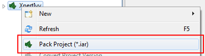
There are two different types of Axon.ivy projects available. Normal Axon.ivy projects are used to develop artifacts. Artifacts in those projects are changed frequently. Once the artifacts of a project are developed and stable you can export the normal Ivy project to an Axon.ivy Archive. Archives are pre-built Ivy projects that are stored in one single *.iar file.
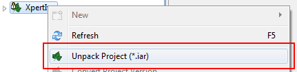
Ivy Archives can be imported to a workspace like normal Ivy projects. All artifacts of an Ivy Archive can be viewed but not edited. Archives already contain all built artifacts. Therefore, they do not have to be built or validated again in the workspace. As a consequence Ivy Archives will improve your workspace build, refresh and update time.
There are multiple ways to create or import Axon.ivy Archives:
Tip
Ivy Archives are not validated automatically. Validation can be started manually by using the context menu.
Here all the projects (including their content) in a given workspace are displayed in a tree view. This is the central component to obtain an overview of the project and to start the specific editors for all Axon.ivy entities.
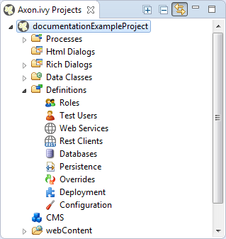
Some of the entries are categorized such as User Dialogs and processes, but in general double-clicking on the leafs opens the corresponding editor. Furthermore a popup menu is provided with the most important interactions:
-
New... - Opens a wizard for creating new Axon.ivy entities such as User Dialogs or processes
-
Refresh - Use this to inform and refresh the project tree whenever the project resources have been changed externally. Axon.ivy with other applications.
-
Close Project - Closes open projects. Closed project are still visible in he workspace but you cannot browse their content or execute them.
-
Open Project - Opens closed projects.
-
Convert Project - Converts a project so that it has the newest format.
-
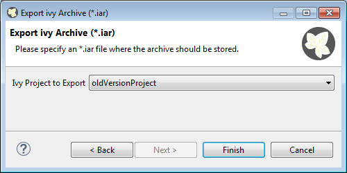
Export Axon.ivy Archive (*.iar) - Starts the Export Wizard to export normal Axon.ivy projects to Axon.ivy Archives.
-
Import - Opens the Import Wizard. Very useful to import new projects from the file system or from a Source Repository such as Subversion or CVS
-
Export - Opens the Export Wizard to exchange certain artifacts with other installations.
-
Rename - Let you rename your resources (User Dialog, Data Class, Process, etc.) while keeping references to those artifacts intact. This menu item is only shown, if the selected resources are eligible for renaming. If renaming is possible, then the rename wizard will be shown, where you can enter a new namespace and/or name for the selected artifact.
Warning
Please, rename your resources only in Axon.ivy and not in Java or Resource perspectives. Trying to do renaming of Axon.ivy artifacts in other perspectives may result in an unusable project.
Tip
Commit your project in SVN before performing any rename operations.
-
Move - Moves the selected resources to another project. The move wizard will be shown, allowing you to select the project to which the resource(s) should be moved.
Note
If Axon.ivy artifacts (such as User Dialogs, Processes or Data Classes) are moved, then the wizard will show an overview of the references (e.g. calls to sub processes) that might be broken by the operation.
-
Copy - Copies the selected resource(s) to the clipboard
-
Paste - Pastes the content of the clipboard into the selected node.
Note
The copy operation is intelligent: it tries to guess the correct location from the contents inside the clipboard, if the selected target node is not suitable for pasting. If there is a conflict upon paste (e.g. because the result would be two resources with the same name) then the copy wizard is presented with a new name suggestion, where you may modify the name and/or namespace of the pasted resource(s) before the operation is executed.
-
Delete - Removes the selected node from the project. Multiple resources may be deleted at once.
Note
If Axon.ivy artifacts (such as Axon.ivy projects, User Dialogs, Processes or Data Classes) should be deleted, then the delete wizard opens and shows an overview of the references that might be broken by the operation.
Tip
Commit your project in SVN before performing any delete operations.
-
Open with - Lets the user choose with which editor the selected entity is opened. It is possible to view a textual representation or a possible external editor for the entity.
-
Team - Gives access to the Team functionality offered by CVS or SVN
-
Compare with - Compares the current version of the entity with an older version from the local history or (if used) from the Source Repository.
-
Replace with - Replaces the current version of the entity with an older version from the local history or (if used) from the Source Repository.
-
Properties - Useful on the project level to set the properties and preferences of the project
The New Axon.ivy Project wizard lets you create a new Axon.ivy project. The wizard consists of three pages, of which two are optional.
On the first page you must specify the settings that are required for the new project. After filling those in, you may already press finish to create the new project.
The second and third page are optional and you do not have to complete them. However, they allow you to specify information with regard to deployment that you would otherwise have to specify at a later point of time, by using the deployment descriptor editor.
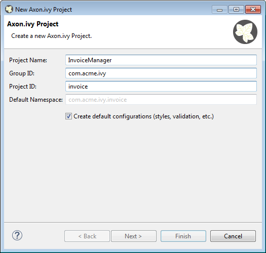
This page lets you define the minimally required settings for a new project.
- Project name
-
Chose a name that describes the contents or the purpose of your project. You are not allowed to use any special characters or spaces.
- Group ID
-
Identifies your project uniquely across all projects. It has to follow the package name rules, what means that has to be at least as a domain name you control, and you can create as many subgroups as you want. e.g.
com.acme.ria. - Project ID
-
You can choose whatever name you want with lowercase letters and no strange symbols, e.g.
usersoruser-manager.During deployment to the engine the concatenated Group ID + Project ID will act as unique identifier of the project, once it is deployed.
- Default namespace
-
Define the default namespace for your project. This namespace will be used as standard namespace for new Axon.ivy artifacts. It is also the namespace into which the project's default data class (
Data) will be generated. - Create default configurations
-
If your project is a base or standalone project (e.g. if it doesn't have any dependencies on required projects) then you should leave this box checked. As a result of this, the new project will be initialized with default configurations in its configuration database.
However, if you're creating a project that is dependent on other projects (see wizard page 2) then you should uncheck this box, because configurations are inherited from required projects. If you'd leave the box checked, then the default configurations that would be created for the new project would possibly shadow (i.e. override) custom configurations with the same name from any required projects that you may have.
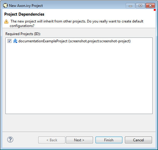
The second page is optional. It allows you to specify any initially project from the workspace as a required project.
- Required Projects
-
Check the projects that the new project should be depend upon. The selected projects will automatically be required with the version that they currently have in the workspace. The maximum version will be left open.
You can always reconfigure the required projects at a later point of time in the Project Deployment editor.
Warning
Please note that adding required projects may produce a warning (as shown in the snapshot above) due to the generated default configurations. The reason for this warning is explained in the First Page section above (Feature Create default configurations).
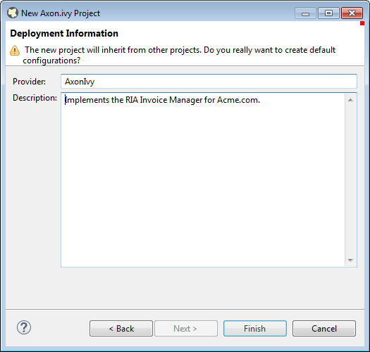
The third page is optional. It allows you to define information about the implementor and the purpose of the new project. This information has documentation value only.
You can always specify and change this information at a later point of time in the Project Deployment editor.
- Provider
-
Define the company or individual that develops and maintains this project.
- Description
-
Describe the purpose of the project's contents or what the application is, that it implements.
You can import existing Axon.ivy projects into your workspace using the Import Wizard. Projects can be exported from the workspace using the Export Wizard (See section Exporting a Project). This allows you to exchange or share your projects with other people.
For Axon.ivy users the following import sources and formats are useful:
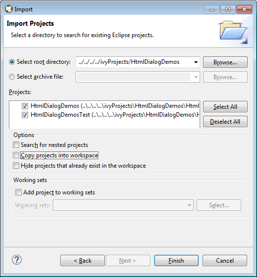
- General > Existing Projects into Workspace
-
Imports a project from a project directory located somewhere in the file system into the workspace. The project directory may or may not be located in the workspace directory.
In the wizard page seen above you can select either the directory where your project(s) resides or a archive file (zip, jar, tar-gz) that contains the project(s). If Axon.ivy find valid projects in the given directory or archive file, they can be (de-)selected for the import and you can decide whether the projects should be copied into your workspace directory or not (which has no effect if a project already is in the workspace directory). After clicking on the button Finish the import is performed and you will find the imported projects in the Axon.ivy Projects View .
- SVN > Checkout Projects from SVN
-
Checks out a project from a subversion source control repository into a new local working copy directory and imports it into the workspace.
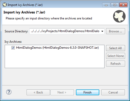
- Axon.ivy > Axon.ivy Archive (*.iar)
-
Imports Axon.ivy Archives (*.iar) into the workspace.
In the wizard page seen above you can select the directory where your Axon.ivy Archives resides. If Axon.ivy finds valid Axon.ivy Archives in the given directory, they can be (de-)selected for the import and you can decide whether the Axon.ivy Archives should be copied into your workspace directory or not (which has no effect if an Axon.ivy Archive already is in the workspace directory). After clicking on the button Finish the import is performed and you will find the imported Axon.ivy Archives in the Axon.ivy Projects View .
- Xpert.ivy > Xpert.ivy 3.9 Project (*.csp)
-
Imports a Xpert.ivy 3.9 project (*.csp) into the workspace. For more information how to import and convert a 3.9 project see chapter Converting old 3.x projects
The Axon.ivy Designer ships with several demo projects that are located in the
applications/samples directory of the Designer installation. Those demo
projects are delivered in the Ivy Archive (*.iar) format and can be imported with the
help of the Sample icon on the welcome page.
Following projects are delivered with the Designer:
| Project name | Demo content |
|---|---|
| ConnectivityDemos | Demonstrates the consuming and providing of REST services with ivy. |
| ErrorHandlingDemos | Samples that demonstrate the Error Handling. |
| HtmlDialogDemos | Demonstrates several JSF components that can be used in Html Dialogs. |
| QuickStartTutorial | The same project that is built in the QuickStart Tutorial. |
| RichDialogDemos | Demonstrates several ULC components that can be used in Rich Dialogs. |
| RuleEngineDemos | Shows how to use the Rule Engine. |
| WorkflowDemos | Demonstrates how to handle typical Workflow use cases, makes use of features like Signals and Business Data. |
Table 2.1. Demo projects in the Designer.
Axon.ivy projects can be exported from the workspace to various output formats using the Export Wizard.
For Axon.ivy users the following output formats are useful:
- General > Archive File
-
Exports projects to a *.zip or *.tar file.
- General > File System
-
Exports projects to the file system.
- Axon.ivy > Axon.ivy Archive (*.iar)
-
Exports a normal Axon.ivy project to an Axon.ivy Archive (*.iar file).
Warning
Not all project artefacts can be converted automatically. After importing a 3.9 project into your workspace there will be some problem and task markers on the imported project. You have to solve these problem and tasks manually before your project runs correctly in Axon.ivy 5.x
To convert an old Xpert.ivy 3.9 project you should do the following steps:
-
Open your old 3.x project with the latest Axon.ivy Designer 3.9 and save it. (This will convert the project to the latest 3.9 version).
-
Import the Xpert.ivy 3.9 project to your workspace.
-
Solve all problem markers.
-
Solve all task markers.
-
Test your imported and converted project.
Warning
Depending on the complexity of your project the steps 3 through 5 can take hours, days or weeks. Be sure that you plan enough time for the conversion and testing of your converted projects.
You may want to try an import and have a look at the problems and tasks view to get an idea how much manually work is necessary.
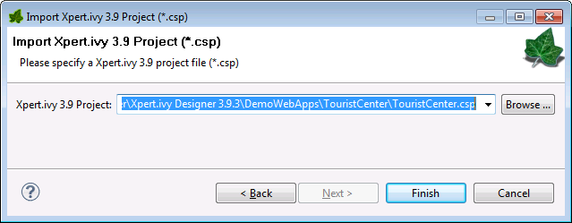
To import a 3.9 project into your workspace use the Import Wizard. Use File > Import ... > Xpert.ivy > Xpert.ivy 3.9 Project (*.csp).
On the Xpert.ivy 3.9 Project Import Wizard you have to specify the Xpert.ivy 3.9 Project File (*.csp):
After you press Finish the following dialog appears:
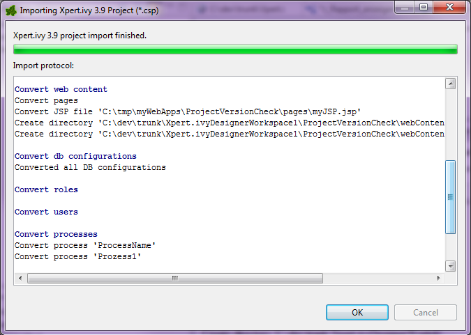
The Import protocol documents the
conversion. After the conversion the protocol is stored in the converted project
directory.
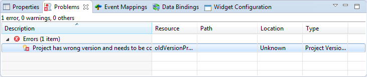
After you have imported the project into your workspace the project will have some problem and tasks markers. You have to solve all problem markers and do the tasks described by the tasks markers manually before your project will run correctly.
For more information about problem markers see chapter Problems View. For more information about task markers see chapter Tasks View.
5.x does not support all the functionality 3.x had provided. Therefore, some parts of your 3.x projects cannot be converted automatically and needs to be converted/redesigned in an other way. The following list shows the major missing functionality of 3.x.
| 3.x functionality | Missing in 4.x/5.x | |
|---|---|---|
| Smart Chart | Smart Chart is not supported. | |
| Navigation / Menu | CMS elements Navigation and Menu and
their APIs are not supported. | |
| List and Recordset functions | Iteration functions like inject(...) or
reject(...) are not supported. | |
| E-Mail Element | Adding a list of attachments to an e-mail is not yet supported | |
| Program Interface Element | The executed Java class needs to be refactored to implement the new interface IUserProcessExtension. | |
| Event Start Element | The executed Java class needs to be refactored to implement the new interface IProcessStartEventBean. | |
| Trigger Element | The element configuration must be converted manually. | |
| WS Process Start Element | The element configuration must be converted manually. | |
| DB Page Element | The DB Page element is not supported. | |
| SOAP Element | The SOAP Element element is not supported. |
Table 2.2. Missing 3.x functionality
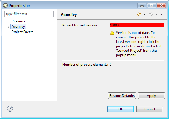
If the project format version changes with a new Axon.ivy release, then old projects will show an error marker, describing them as out of date or having an invalid version. This can happen, when the technical format for Axon.ivy projects changes with a new Axon.ivy release (e.g. the way how some artifacts are stored may be changed, new artifacts may be introduced, etc.). :
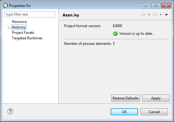
If you inspect your project's properties, the main page will show you the actual project version and inform you whether it is up to date or not (see Project Properties below):
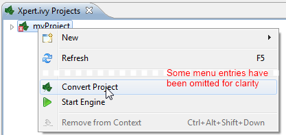
Axon.ivy can convert your old projects automatically to the newest project format for you. During this process, all existing artifacts will be converted (if necessary) so as to work with the new Axon.ivy version, and any missing but required artifacts will be added.
To run the project conversion, select the project's node in the Axon.ivy project view and right click to bring up the context menu. Select Convert Project to initiate the conversion. A log screen will appear that documents the conversion process (this log is also saved in the logs/ folder inside your project), and which will inform you about whether the conversion was successful or not.
Note
You can not use this feature to convert 3.x projects. It only works for 4.x project versions.
Warning
It is absolutely recommended that you create a copy of your project before invoking the conversion. Alternatively you can have your project under version control. In this case, make sure that all your projects are checked in, before you invoke the conversion, so that you can easily roll back (revert) to the old version, if conversion should fail for some reason.
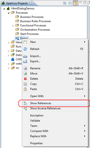
You can access the properties and preferences of a project either over the item Properties in the popup menu of the Axon.ivy Projects View or over the menu item Project -> Properties. Here you can redefine almost all of the global workspace preferences and override them with project-specific values.
Additionally, the project preferences allow you to define values for some project-only properties, that do not have a global default value. Those are described in the sections below.
The main project properties page shows information about the project.

- Project format version
-
Shows the version of the project format. If the project was created with an old version of Axon.ivy, this is indicated with an warning message. Consult the Chapter Project Conversion to learn how to convert your project to a new version of the project format.
- Number of process Elements
-
Shows the number of process elements in this project.
The languages in the CMS and the defaults for HTML dialog pages can be set here.
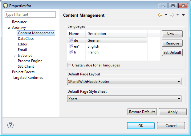
In the list at the top you can add and remove languages to/from the CMS and you can set the default language. Just below you can define whether Axon.ivy should automatically create a value for every language of the CMS if you create a new Content Object. Do not use this option if you do not need content in multiple languages or if you export the CMS content to translate it. Use the option if you know that you need to translate the vast majority of Content Objects within the Axon.ivy Designer
Furthermore, you have the choice between different HTML page layouts and CSS style sheets for use as default values for HTML dialog pages.
Allows you to specify the default namespace and the name of the project Data Class.
- Automatically imported classes
-
Allows you to specify fully qualified class names which should be automatically available with their simple class names in every ivy script code.
With these preferences you can adjust the Java settings of the project.
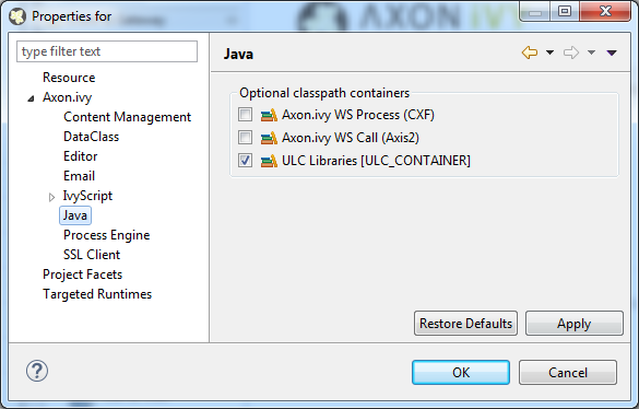
- Optional classpath containers
-
Defines optional libraries which can be accessed by Java or IvyScript code of the project.
If migrated your project from 6.0 or older you may have used CXF or AXIS2 libraries by accident in your code. With the classpath container checkboxes you can put these libraries on the classpath to avoid compilation or runtime errors.
Each Axon.ivy project has a deployment descriptor. The deployment descriptor defines various properties of a project that are important with respect to deployment on the engine. Specifically the descriptor defines:
-
An unique project ID (i.e. a fully qualified symbolic name) for the project, by which it can be identified and referenced. Also, a current development version of the project is defined (please note that this version may, but does not necessarily have to be, identical with the project model version on the engine into which the project will eventually be deployed).
-
The dependencies of a project to other projects and the exact version range of those projects that must be available in order for the project to work. Once a project is referenced in this way, it's artifacts may be used inside the referencing project. This applies especially to the following artifacts: User Dialogs, Data Classes, Web Service Configurations, CMS Entries, Configurations, Java classes or Java libraries (JAR files).
-
Information about the implementor of the project and it's purpose.
The following figure illustrates the above:
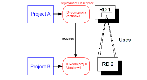
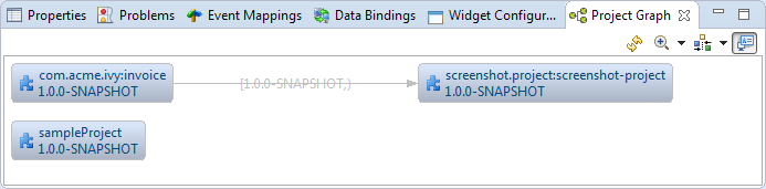
Since referenced projects may in turn reference other projects, a whole (acyclic) dependency graph may be constructed this way. All artifacts of projects that are reachable from some project in this way (i.e. by following the arrows) can be used.
The following figure illustrates this feature. For example, a User Dialog defined in Project D may be used in Project A. A Data Class that is defined in Project E may also be used in Project A. However, it is not possible to use a Sub Process defined in Project B from Project C (unless Project B is added as required project in the deployment descriptor of Project C).
The search order to look up reused artifacts is breadth first. The order, in which directly referenced projects are looked up, can be defined in the Deployment Descriptor editor.
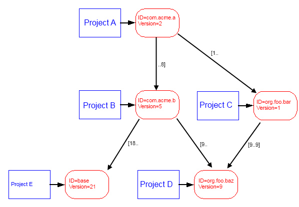
Projects may be required with a specific version or within a specific version range. This is also illustrated in the above figure.
When deploying projects on the engine, the availability of the required projects (and their versions) is checked. If the required project versions can not be resolved, then a project can not be deployed. Therefore projects must be deployed bottom up, i.e. one must start by deploying first the required projects that are lowest in the dependency hierarchy.
The Deployment Descriptor editor allows to edit a project's deployment properties as well as the required projects and their version ranges as described above. Most of those properties can already be specified in the New Project Wizard, when a project is initially created.
The deployment descriptor editor consists of two tabs:
-
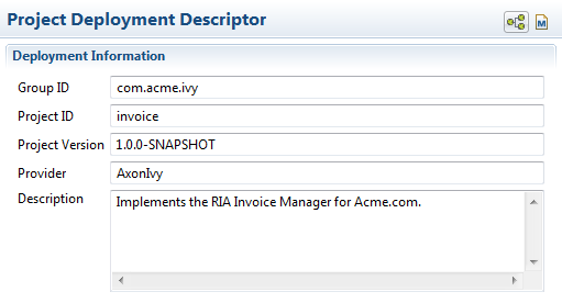
The Deployment tab is used to configure the project's own deployment information.
-
The Required Projects tab is used to define other projects (possibly in a specific version) that the project depends on.
The deployment description is stored as Maven pom.xml so that Ivy Projects can be built on a continuous integration server. See “Continuous Integration”
Axon.ivy Project Tree -> double click on the Deployment node inside the project tree ( )
)
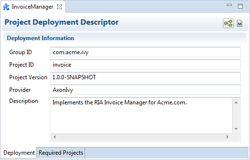
- Group ID
-
Identifies your project uniquely across all projects. It has to follow the package name rules, what means that has to be at least as a domain name you control, and you can create as many subgroups as you want. e.g.
com.acme.ria. . - Project ID
-
You can choose whatever name you want with lowercase letters and no strange symbols, e.g.
usersoruser-manager.During deployment to the engine the concatenated Group ID + Project ID will act as unique identifier of the project, once it is deployed.
- Project Version
-
The current development version of the project.
- Provider
-
The name of the user or company that implements and maintains (i.e. provides) the project. The provider setting has not functional purpose. It is for documentation only.
- Description
-
A (short) description of the project's purpose and contents. The description setting has no functional purpose. It is for documentation only.
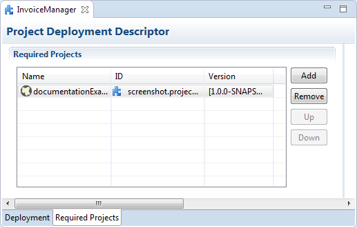
- Required Projects
-
A table shows the list of the required projects, both with their name and their ID (as defined in the project's deployment descriptor). The table also shows the version range in which the referenced project must be available.
- Name
-
The display name of the required project (how it is shown in the workspace).
- ID
-
The unique identifier of the required project.
- Version
-
The range specification of the version that the referenced project is required to have.
Note that the order in the table defines the order how referenced artifacts are searched (Use the Up Button and Down Button to change the order). The general search order in the dependency graph is breadth first, but the order that you define here is the search order that will be used at a specific node when searching the graph.
Clicking the Add button brings up a dialog with a selection box, in which any of the projects that are currently present in the workspace may be selected as required project. Closed projects or projects, that are already (directly) required, can not be selected.
Selecting an entry in the table and subsequently clicking the Remove button removes a project dependency.
- Required Project Details
-
Shows the details of the currently selected project.
- Group and Project ID
-
The identifiers of the required project (not editable).
- Maximum Version
-
Optionally specify the maximum version that the required project needs to have. Choose whether you want to include or exclude this maximal version by checking the Inclusive box
- Minimum Version
-
Optionally specify the minimum version that the required project needs to have. Choose whether you want to include or exclude this minimal version by checking the Inclusive box
Warning
Beware of cycles in the project dependencies! You should never require a project B from a project A, if B also requires A (or if B requires any project that in turn requires A, which would form a larger cycle). Error markers will be displayed when the workspace is built, and cycles are detected, because this condition can lead to endless recursion and other unpredictable behavior when looking up artifacts.
The Project Graph view shows the dependency graph of all projects in the workspace.
 Refreshes the complete graph. Manually moved nodes will be
re-arranged by the auto layout algorithm.
Refreshes the complete graph. Manually moved nodes will be
re-arranged by the auto layout algorithm.
 Selects the zoom level of the view.
 Selects the layout algorithm that arranges the nodes and
dependency edges in the view.
Selects the layout algorithm that arranges the nodes and
dependency edges in the view.
 Automatically opens the Project Graph whenever a Library
Descriptor Editor is opened.
Automatically opens the Project Graph whenever a Library
Descriptor Editor is opened.
-
Double click on a node to open its Library Descriptor Editor
-
Drag a node to improve the layout
-
Click on a node to highlight it
Axon.ivy comes with various validators which verify that projects and it's resources do not have any errors. After a resource has changed the responsible validator will run automatically and report errors or warnings.
To manually validate a project or a resource you can right click on it and select Validate.
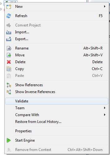
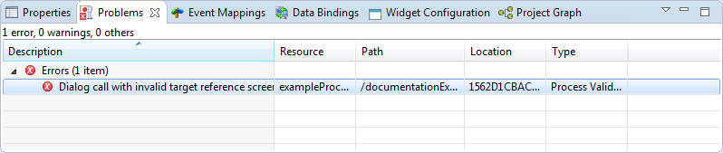
After the validation the errors are shown in the Problems view.
This chapter introduces Axon.ivy processes and how to work with them. The creation and logical organisation of processes is explained as well as the functionality of the Process editor and the different kinds of processes.
There are different kinds of processes. Their use and capabilities are explained in the sections below.
Business processes are the regular kind of processes that are used to implement business cases. Business processes contain starts that can be selected by any user from his/her workflow list or from the list of star table processes.
An embedded subprocess is essentially a syntactical collapse of elements into a single element to hide details from process design. They are available in all other process kinds. The hierarchy of embedded subprocesses is potentially indefinite, i.e. you can create further embedded subs inside an already existing subprocess.
Since embedded subprocesses are simply a structural means for process diagram simplification, no mapping of data is required when entering or leaving this kind of subprocess (i.e. inside an embedded subprocess the same data is available as inside the caller process).
Warning
Wrapping process elements into an embedded subprocess does not influence the functionality of most process elements. But the wrapping influences the way process elements are addressed by Axon.ivy. This may cause incompatibilities with older versions of the process and will hinder you to deploy such a process over an already deployed older version of the process. The process elements that may cause such incompatibilities are:
An independent subprocess (callable) is a process, that can be called from any other process with the call subprocess element. Independent subprocesses can be used to factor out frequently used functionality which can then be reused by any other process.
Because callables are independent implementations of processes (or parts of process logic) they have an own Data Class which might not match the caller's data. Therefore parameters need to be mapped in both directions when entering and leaving an independent subprocess.
To create an independent subprocess, select the callable process option from the New Process wizard. The created process will contain special start and end elements that must encompass the process implementation.
Web Service processes are a special case of independent subprocesses. A Web Service process can be started (i.e. called) from any other application (or from another process) by using the Web Service call element or any other SOAP web service compatible client..
A web service process will provide a web service with one or more operations, which are defined by the Web Service Process Start elements within the process. Each of these start elements have their own input and output parameters that will be mapped to and from the process data.
Due to the nature of web services, which are intended to be called by another applications and not by a user directly, no user-interaction (HTML or User Dialogs) is allowed within such a process. If the process does contain user-interaction an exception will be thrown.
To create a web service process, select the Web Service Process option from the New Process wizard. The created process will contain special start and end elements that must encompass the process implementation.
User Dialog logic processes are the implementation of the behavior of User Dialogs, the controller in the MVC pattern. A whole new set of elements is available for this kind of processes (from the User Dialog drawer on the process editor palette), while other elements (such as task switch or HTML page) are not available for conceptual reasons.
A User Dialog logic process is invoked with an User Dialog element inside a business process. Its execution starts with an init start element and ends with a dialog exit element. The two elements do not need to have a direct connection (in fact they never have). Once a User Dialog process is running, it is driven by user interface events which will trigger individual sub processes.
Note
Calling a process based User Dialog (and thus executing its logic) can (or rather should) be seen as equivalent to calling of a callable process with the sole difference that the User Dialog offers a user interface that allows a user to interact with the process logic directly.
However, from an abstract point of view, a User Dialog is nothing else than a function call. It is invoked with a list of (optional) arguments and returns a list of result values. This is exactly the same behavior as a callable process offers.
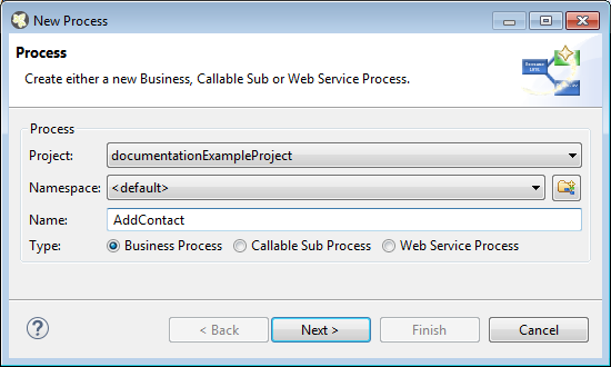
The New Process Wizard lets you create a new Business, Callable Sub or Web Service Process.
- Project
-
Choose the project where the new process should be created.
- Namespace
-
Select a group where the new process will be inserted (this is roughly equivalent to a namespace). Select the
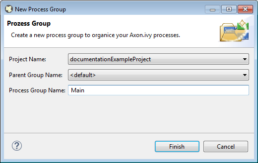
<default>process group to create a process directly below the project's processes folder (i.e. equal to "no group"). You can click on the group folder button to open the New Process Group Wizard, if you want to create a new group "on the fly". The process groups are listed relative to the project's process folder. - Name
-
Enter the name of the new process.
- Type
-
Business Process: This option is the default option an creates a normal standard business process. Use this option to implement your business logic.
Callable Sub Process: This option creates a callable sub process including a process-call-start element and a process-call-end element. You need to implement your process between those two elements. It is allowed to have multiple Process Starts and Process End elements in a callable process.
Web Service Process: This option creates a web service process which can be called from other systems. WS Start and WS End elements will be created automatically and you can implement your process between these elements. Please note that no user interaction may occur in a web service process.
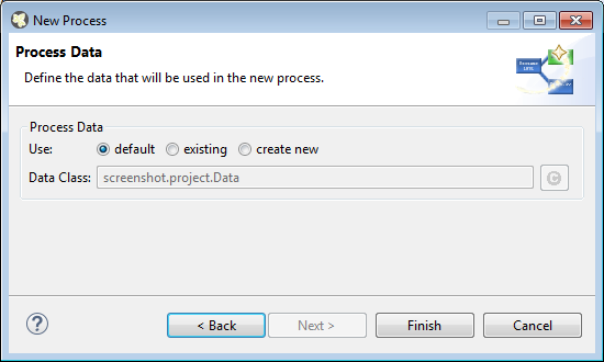
- Process Data
-
default: Select this option to use the project's default data class as data structure for the new process.
existing: Select this option to choose an already existing data class as data structure for the new process. Any existing Data Class can be chosen with the class selector button on the right side. It is strongly recommended to select a data class from the project where the process will be created in order to avoid dependencies on the implementation of another project.
create new: Select this option to create a new, empty data class that will be associated with the new process. Enter the name of the new data class to create (including namespace). Initially a data class name that is based on the new process' name and group will be suggested, but you're free to change it.
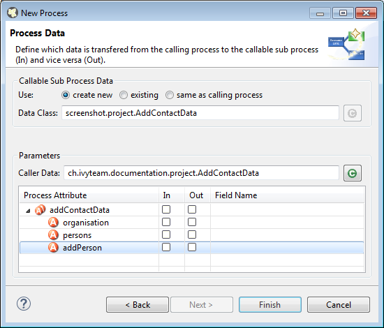
Callable Sub Processes often consume or return data from a high level process. The data which is passed to and given back to the caller process can be easily mapped within this page.
- Callable Sub Process Data
-
Defines the Data Class which is used within the Process to create. The simple mapping parameters below are only available if a new Data Class is created or when the Callable Sub Process uses the same Data Class as the caller Process.
- Parameters
-
The Caller Data references the Data Class from the Caller Process. The fields of this Data Class can be automatically mapped to the Callable Sub Process Data.
In the mapping table below the Caller Data the In and Out arguments for the new Process can be defined. If any mappings are chosen, the Wizard will automatically configure the Call Sub Start Event, it's internal input mapping (param > in) and it's output mapping (out > result). The calling process element of the high level process will also be inscribed with input- & output mappings, if the new Process Wizard was opened from the Call Sub inscription step.
The New Process Group wizard lets you create a new grouping folder for business processes. Process groups can be nested.
Note
The process group is just used to categorize similar processes. A process is always treated independent from its parent process group(s)
Processes exported in Axon.ivy Modeler as BPMN XML Export can be imported into the Designer through the Axon.ivy Modeler Process importer.
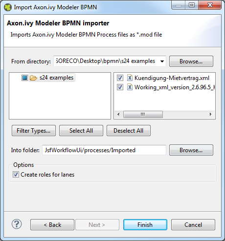
- From directory
-
A directory containing the Modeler BPMN Files. It's allowed proved a directory structure.
- File selection
-
Selection of any valid Modeler BPMN Files within the From directory
- Into folder
-
A directory pointing to a process group. All imported processes will be stored in this process group. In case the specified folder does not exist, it will be created automatically.
- Option: Create roles for lanes
-
If the Modeler BPMN Processes selected for import contain lanes, it's possible to create new roles from the lane names in Axon.ivy Designer automatically trough the import by this option.
The Axon.ivy Designer supports the import of processes from the Axon.ivy Modeler 3.1.0. The internal version in the exported XML file is 97.1.0. Other versions or plain BPMN2 XML files might be imported anyway, but they are not supported.
<bpmn:definitions ... exporter="GBTEC BIC" exporterVersion="97.1.0">
Axon.ivy Modeler and Axon.ivy Designer are tools to serve different needs, hence it's no possible to map any process element of the Modeler to exactly one corresponding element in Designer through the importer. As a consequence, the importer follows to main goals:
-
Achieve as much recognition of the Modeler process as possible
-
Provide a good basis for further implementation of process design
The mapping follows following rules:
- Pools and lanes
-
Position, size and labels of swimlanes are adopted from the Modeler process.
- Position and size of process elements
-
Position and size of process element nodes as well as any waypoints of process arc are adopted from the Modeler process.
- Process events
-
In general, all process events are mapped directly to an event in the Designer.
- Sub processes
-
Sub processes are mapped to an Embedded Sub element in the Designer.
- Gateways
-
Exclusive gateways are mapped to an Alternative. Any other gateways are mapped to a Task Switch.
- Tasks
-
In general, task process elements are mapped to a BPMN Activity in the Designer. If possible, the process element is mapped to a specific element e.g. User or Manual.
The BPMN Activity elements behave basically similar to an Embedded Sub element, so it is possible, to implement the behavior of this process element at a lower level without changing the high level appearance of the process.
- Links to other processes
-
Links to other processes are mapped to a Subprocess Call in the Designer, the call target remains empty after import.
- Text annotations
-
Text annotations are mapped as Annotation in the Designer.
- Data objects
-
Data objects are mapped as Annotation in the Designer, to distinguish them from text annotations, the differ in size and color.
- Sequence Flows
-
Sequence Flows are mapped as Connector in the Designer.
- Message Flows
-
Message Flows are mapped as Message Flow in the Designer.
Like the process elements that are used inside a process, the process itself has an inscription that allows to specify and edit a processes properties. To open and show a the inscription mask of a process you simply select the process in the Ivy Projects View, right-click and select inscription from the pop-up menu.
The common name tab allows to specify name, description and associated documents for each process.
The values tab allows to specify the data class that will be used to define the process's data structure.
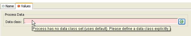
Each process must be associated with a data class, otherwise the tab will show an error. The used data class is initially specified with the New Process Wizard, but you may change this association at any later time.
You can use the (C) button next to the data class field to select any existing data class that is visible to the edited process. Please note that it is strongly recommended that you only set data classes that are defined in the same project as the process in order to avoid dependencies on the specific implementation of another project.
It is legal for two processes to specify the same data class. This can be desired if the processes operate on the same set of data (e.g. sub processes) and it may facilitate the mapping in some cases.
The Web Service Process tab is only available on web service processes and allows to specify the web service configuration.
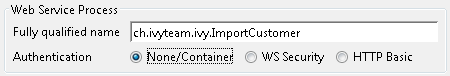
The Fully qualified Web Service name will be used to generate the web service class and the WSDL. The namespace part will be used as targetNamespace in the WSDL. Choose this name carefully since it should not be modified anymore as soon as clients start using the web service.
The Web Service authentication options allows you to specify how clients are authenticated when invoking the web service. You can select one of the following available authentication methods:
- None/Container
-
Authentication is not handled by the web service element. However, if the web container (Tomcat) or a web server (Microsoft IIS/Apache) handles user authentication, the user is passed through to Axon.ivy (e.g. Single Sign On).
- WS Security
-
UsernameToken with Password will be sent in clear-text to the ivy engine.
Warning
Only use this option in a trusted network or over a secure connection (e.g. HTTPS).
- HTTP Basic
-
Username and Password will be sent in clear-text to the ivy engine using standard HTTP Basic authentication mechanism.
Note
HTTP Basic is the only authentication option that is supported by Web Service processes and Web Service process elements in common. It can therefore be used to call a Web Service process from a Web Service process element if authentication is required.
Warning
Only use this option in a trusted network or over a secure connection (e.g. HTTPS).
If the web container (Tomcat) or a web server (Microsoft IIS/Apache) already handels user authentication, the user is passed through to Axon.ivy without doing an additional HTTP Basic authentication.
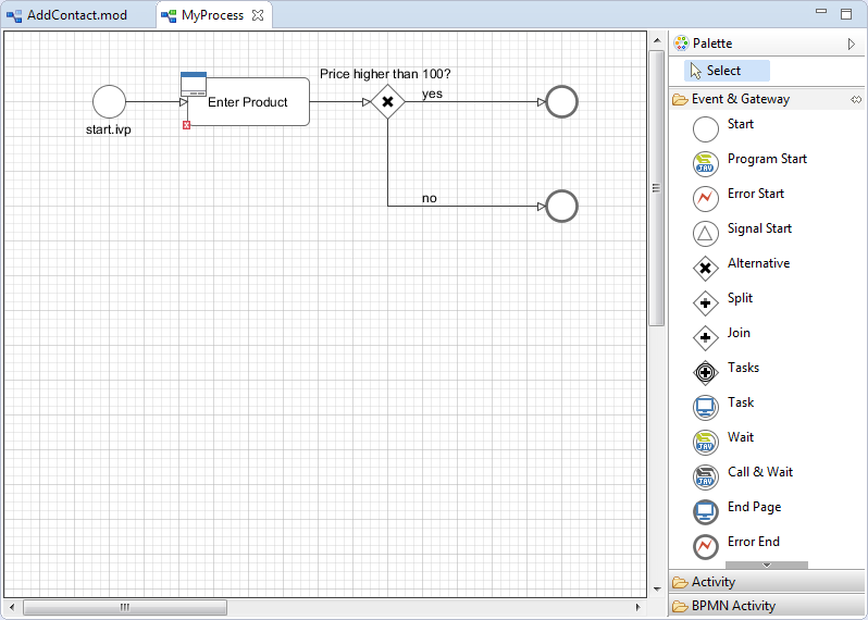
The Process editor is used to design and edit the different process kinds (mostly business and User Dialog logic processes). The Process editor consists of two parts:
-
the editor area where the process logic is constructed element for element and
-
the palette where the elements that are to be placed inside the process are selected

The palette shows the process elements that are available for a specific process kind. The set of available process elements may vary for different process kinds.
Tip
The purpose and configuration of all available process elements are described in detail in the process elements reference chapter.
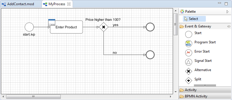
Processes are designed, drawn and modified in the process editor area. Select an element from the palette, then click in the process editor area to place it. Click and drag elements to replace them.
Arrows are drawn between two elements by clicking on the first element, then holding the left mouse button down until releasing on the second element.
You have four context menus available in the Process editor: the editor menu, the element menu, the arrow menu and the selection menu.
To open the editor menu right click anywhere on the editor area's canvas (i.e. background). The following actions are available:
- Leave Subprocess
-
Will jump out of an embedded subprocess to the process that contains the Embedded Sub element.
- Select All
-
Selects all process elements.
- Copy (as Image)
-
Copies the whole process (as image only) to clipboard.
- Insert template
-
Inserts an existing process template. Opens a selection dialog to choose the template to be inserted, then inserts the selected template at the current mouse position. All of currently defined process templates are also available from the Process Template View.
- Paste
-
Pastes a previously copied or cut element into the process at the current mouse position.
- Undo
-
Undo the last drawing command. The process editor keeps up to 100 commands in the history buffer that can be undone.
- Zoom In
-
Zoom in to get a close-up view of the process model. The view is enlarged by a factor of 20%. With a wheel mouse, you can also zoom in with the wheel together with the Ctrl key.
- Zoom Out
-
Zoom out to see more of the process model at a reduced size. The view is reduced by a factor of 20%. With a wheel mouse, you can also zoom out with the wheel together with the Ctrl key.
- Zoom 100%
-
Reset the zoom factor to the default size.
- Change orientation of swimlanes
-
Changes the orientation of pools and lanes from horizontal to vertical or vice versa.
- Add pool
-
Adds another pool before the swimlane at the current mouse position.
- Add lane
-
Adds another lane before the lane or inside the pool at the current mouse position.
- Edit pool/lane
-
Opens the configuration of the pool or lane at the current mouse position
- Remove pool/lane
-
Removes the pool or lane at the current mouse position
- Inscribe Process
-
Opens the configuration editor of the process.
To open the element menu right click on an process element. The following actions are available:
- Copy
-
See selection menu.
- Cut
-
See selection menu.
- Inscribe
-
Opens the configuration editor of the process element.
- Wrap Text
-
Places the name of the element inside the element's icon. The icon size is stretched accordingly.
- Move Text
-
Replaces the element's text with a box that can be moved around. You can also achieve this by simply clicking and dragging an element's associated text.
- Style
-
See selection menu.
- Open Document Reference
-
Opens document URLs which are configured in the elements 'Name' inscription tab.
- Attach boundary event
-
Attaches an additional boundary event to the currently selected activity.
- Breakpoint
-
Add a regular or conditional breakpoint to the element or remove all breakpoints from the element.
- Connect
-
Creates an arrow that starts at this element. Click on another element to create a connection between the two elements. You can also create an arrow by clicking on the process element where the arrow should start and then move the mouse while you keep the mouse button pressed to the process element where the arrow should end.
- Disconnect
-
Disconnects this element from another element. Click on another element to remove the connection between the two elements.
- Move
-
See selection menu.
- Extended Functions
-
Select from extended layout functions for the element. You can reset the default size of an accidentally resized element. If elements are placed on top of each other you may send an element to the back or bring it to the front of the element stack.
- Delete Element
-
Deletes the element.
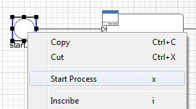
The visibility of the following menu entries are depending on the type of the process element:
- Start Process
-
Starts the process that begins at the process element.
- Send Signal
-
Opens a dialog to send a signal. The dialog uses the signal code configured on the process element as default value.
- Enter Subprocess
-
Enters the embedded subprocess and shows the encapsulated process.
- Toggle Transparency
-
Changes the transparency state of the embedded subprocess. This either hides the process that is encapsulated by the embedded sub element or makes it visible.
- Unwrap Subprocess
-
The elements encapsulated by the embedded subprocess are placed into the current process.
- Change type
-
Converts the Embedded Sub into another subprocess type (e.g. from BPMN User Activity to BPMN Send Activity). The inner fields will be kept, but its field ids will change. This makes the Process Model incompatible as when elements are wrapped for the first time. See “Embedded Subprocess”
- Search callers of this process
-
Displays all callers of a Start in the Search view.
- Search callers of this exception element
-
Displays all process elements that call an Exception Start when an exception occurred.
- Jump to connnected element
-
Will jump out of an embedded subprocess to the process that contains the Embedded Sub element and selects the process element that is connected with the Embedded Start or End Event.
- Jump to referenced process
-
Opens the process that is referenced by the process element.
- Jump to User Dialog Process
-
Opens the process of the User Dialog that is referenced by the process element.
- Edit Page
-
Opens the web page configured on the process element. If no page is configured then the Create New Page dialog is opened.
- Edit Java Class
-
Opens the Java editor with the Java class configured on the process element. If no Java class is configured the New Bean Class Wizard is opened.
- Edit User Dialog
-
Opens the view editor (e.g. ULC Visual Editor or JSF Editor) for the selected User Dialog.
To open the arrow menu right click on a an arrow. The following actions are available:
- Inscribe
-
Opens the configuration editor of the arrow that the mouse is placed over.
- Move Text
-
Replaces the arrow's text with a box that can be moved around. You can also achieve this by simply clicking and dragging the arrow's associated text.
- Bend
-
Relayouts the arrow's path on the editor's grid (use only rectangular angles).
- Straighten
-
Relayouts the arrow's path into a direct line without any angles.
- Color
-
Changes the color of the arrow.
- Bring to front
-
If elements and arrows are placed on top of each other then this action brings the one with the cursor over it to the front of the element stack.
- Send to back
-
If elements and arrows are placed on top of each other then this action sends the one with the cursor over it to the back of the element stack.
- Reconnect
-
Detaches the selected arrow's head from the element it is connected to and let's you reconnect the arrow to another element.
- Delete connector
-
Deletes the selected arrow.
To open the selection menu right click on a selected element or a group of selected elements (i.e. selection frame is visible). The following actions are available:
- Copy
-
Copies the selection to the clipboard.
- Cut
-
Copies the selection to the clipboard and deletes all contained elements from the process.
- Style
-
Sets the style of the selected elements to a style in the predefined list of styles.
- Auto Align
-
Aligns the selected elements horizontally and vertically.
- Same Width
-
Assigns the same width to all of the selected elements. The resulting width is determined by the widest element in the selection.
- Same Height
-
Assigns the same height to all of the selected elements. The resulting height is determined by the highest element in the selection.
- Same Width and Height
-
Combination of the menus Same Width and Same Height.
- Set to default size
-
Resets the size of the selected elements to their default sizes.
- Wrap into Subprocess
-
Creates an embedded subprocess from the selected elements.
- Create template
-
Creates a new process template from the selected elements. After prompting for a name for the selection, the new template will be available from the Process Template View.
- Delete selection
-
Deletes all of the selected elements from the process.
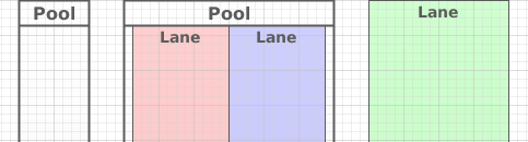
Processes can be visually structured by using pools and lanes. Pools and lanes are colored background swimlanes with a label that are placed behind the process logic. Swimlanes can have a horizontal or vertical orientation.
Swimlanes are available for all process kinds and are typically used to visualize organisations, roles, responsibility assignments or systems for process elements or sections of process logic.
A pool or lane can be widened or narrowed by dragging it's border/edge with the mouse. By default, the position of process elements lying outside the modified lane are adjusted accordingly. By pressing the Shift-Key during the drag, you can omit the automatic adjustment of process elements.
Note
Please note, that pools and lanes do not have any syntactical meaning whatsoever; their purpose is purely semantical. A pool or lane is not a container that elements are placed in or associated with. They are simply a structured "coloring" of the process' background; they do not grow or shrink when you change the processes logic and need to be adjusted manually.
The Axon.ivy Process Model Reporting Wizard lets you create customized reports of your process models.
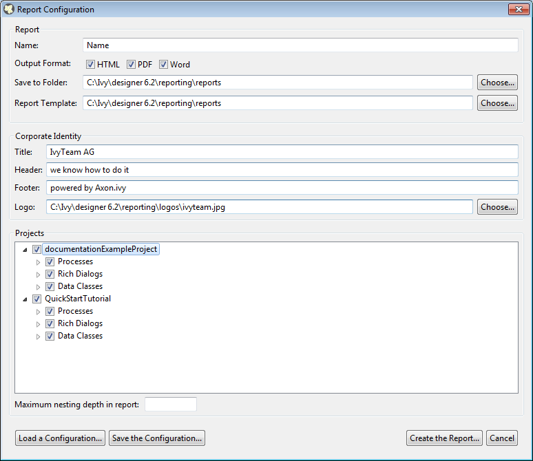
- Name
-
The name of the report that will be created. This name should be without file name extension. E.g. use "MyReport" instead of "MyReport.pdf".
- Output Format
-
The report output format. Currently this can be HTML, PDF or DOC. You can also select multiple report formats that should be created simultaneously.
- Save to Folder
-
Choose the location where the reports should be generated to. The default destination where reports are stored is IvyDesigner/reporting/reports/.
- Report Template
-
Choose a report template, also known as BIRT report design file(*.rptdesign) which defines the structure and contents of your report. There are some BIRT report designs provided by default (e.g. Default.rptdesign). Please use the predefined report designs unless you want to create a custom report design.
- Corporate Identity
-
This group of text fields provides you some additional, optional information to customize your report.
-
Title: Select a Title that will be shown on the first page of your report.
-
Header: Select a Header for the report, that will be shown on every page.
-
Footer: Select a Footer for the report, that will be shown on every page.
-
Logo: Select a Company Logo Image that will be displayed on the first page of your report.
-
- Projects
-
This Tree shows the currently active Projects that can be reported. You may check or uncheck the individual Process Models, Process Groups, Processes, Rich Dialogs or Data Classes that are to be reported.
- Maximum nesting depth
-
Choose the maximum depth up to which nested embedded sub processes should be reported. By default and when the field is empty all embedded sub processes are reported.
- Cancel Button
-
To cancel report creation. The current report configuration settings will be stored to your_ivy_workspace/.metadata/.plugins/ch.ivyteam.ivy.designer.reporting.ui/lastReportconfiguration.xml.
- Save the Configuration...
-
To save the report configuration you have entered up to now into an XML report configuration file (*.rptconfig). This allows you to store multiple configurations for different types of reports and reuse them later. Note that currently the selected Projects, Processes, Rich Dialogs etc. are not remembered, as they might not be available at loading time. The default place where the report configurations are stored is in IvyDesigner/reporting/configurations/.
- Load a Configuration...
-
This allows you to load a previously stored report configuration files (*.rptconfig).
- Create the Report...
-
This will start the generation of the reports. While the report generation you will be informed about its progress. After the report has been generated a confirmation window will provide you with links to the generated reports. The default destination where reports are stored is IvyDesigner/reporting/reports/.
The report configuration will be stored to your_ivy_workspace/.metadata/.plugins/ch.ivyteam.ivy.designer.reporting.ui/lastReportconfiguration.xml
The outline view displays all elements of the process which is currently opened in the process editor.
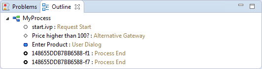
The outline view has the following features:
- Selection
-
Process elements which are selected in the outline view are selected in the process editor and vice versa, which helps to search and manipulate elements, especially in large processes.
- Classification
-
Elements are grouped by their BPMN type, where the element type is visualized with an icon in front of the element name. The element categories are start events
 , intermediate events
  , end events
  , gateways
  and tasks
  .
.
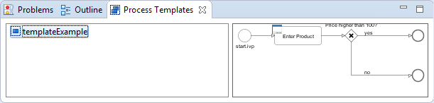
The process template view displays the currently defined process templates. A process template is essentially a selection of process elements that is stored under a specific name. Once defined, process templates can be inserted into any existing process, either by drag and drop or by selection from a dialog. New process templates can be added to the template store by pressing 't' on a selection of elements in the Process Editor.
The process template view has the following features:
- Preview
-
A preview for each selected template will be shown on the right-hand side of the process template view, showing it's structure in detail.
- Drag-and-drop
-
Templates can be dragged and dropped on the process editor. Press and hold the mouse down over a template name and drag it over to the process editor to insert the template.
- Context menu
-
Selected templates can be renamed and deleted using the context menu or by pressing 'R' or 'DEL' keys, respectively.
The problems view displays errors and warnings (problem markers) that exists in yours projects. You can double click an error or warning in the view to open the associated editor.
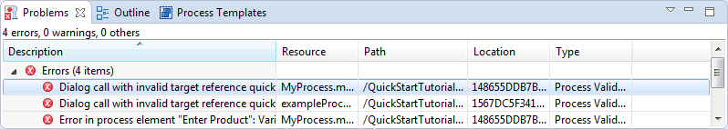
In the process editor process elements that have errors are marked with an error overlay icon.
The tasks view displays tasks that exists in yours projects. You can double click a task to open the associated editor.
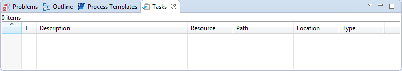
In the process editor process elements that have tasks are marked with a task overlay icon.
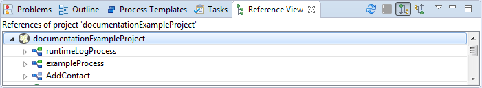
The Reference view shows the references between the various Axon.ivy project artifacts. A reference of an artifact is everything which is used/called from the artifact (e.g. call to a callable process or User Dialog) or which is embedded in the artifact (e.g. embedded sub element in a process or processes inside a project). Inverse references are the opposite of references. This means an inverse reference of an artifact is everything which uses/calls the artifact or which contains it.
Tip
To work with references of process elements, there are also some useful features on the Process Editor “Element Menu”
The following table shows all supported references between Axon.ivy project artifacts.
| contains | uses / calls | |||||||||||
| Projects | Processes | Callables | User Dialogs | Embedded Sub | Data Classes | Projects | Processes | Callables | User Dialogs | Embedded Subs | Data Classes | |
| Project | X | X | X | X | X | |||||||
| Process | X | X | X | X[a] | X | |||||||
| Callable | X | X[b] | X[a] | X | ||||||||
| User Dialog | X[a] |
X | X | |||||||||
| Embedded Sub | X | X | X[a] | |||||||||
| Data Class (Entity Class) | X | |||||||||||
[a] User Dialogs can be referenced also from other projects. [b] Callable can reference itself. | ||||||||||||
Table 2.3. Overview over the supported references
Window > Show View > Reference View
Right click on a project, process, User Dialog or embedded sub element in the project tree > Show References or Show Inverse References
The Reference view has the following functions:
- Refresh (
 )
) -
This function reloads the actual showed references.
- Stop (
 )
) -
This function stops the calculation of references.
- Show References (
 )
) -
This option shows the references of the actual root object.
- Show Inverse References (
 )
) -
This option shows the inverse references of the actual root object.
This chapter deals with Axon.ivy debugging and simulation features. Processes, workflows, User Dialogs and changes on these should be tested before being deployed on an Axon.ivy production Engine. Therefore the Designer allows to simulate processes on your local computer, to debug it in depth and to inspect the execution history of all variable values. Hereby the process flow can be animated to visually observe the actual process execution sequence.
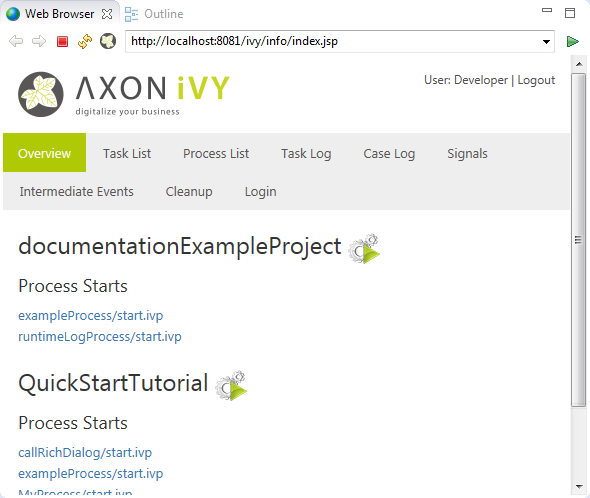
A simulation can be started directly on the Request Start element or on the Designer Workflow UI Overview page displayed either in the browser view of the Process Development Perspective or in a separate browser window, depending on the setting in the corresponding preference. This Process Start Overview web page shows all processes that can be started by clicking on the link.
Also the Web Services are displayed on the Process Start Overview page. By clicking a Web Service Process link, the corresponding WSDL is displayed.
Tip
You can switch off the simulation of Process Start Events and Intermediate Process Events when you want to simulate or test other parts of a projects. Just set the corresponding options in the preferences
You are able to control the simulation and to influence the animation using the actions in the toolbar or the Axon.ivy menu.
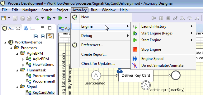
- Starting the engine and show overview page
-
Select the entry
 in the
menu or the button
in the
menu or the button  in the toolbar to start the
Simulation Engine, open the Process Development Perspective and refresh the Process Start Overview page.
in the toolbar to start the
Simulation Engine, open the Process Development Perspective and refresh the Process Start Overview page. - Starting the engine
-
Select the entry
 in the menu or the button
 in the toolbar to start the
Simulation Engine and refresh the Process Start Overview page but
without opening the Process Development Perspective.
in the toolbar to start the
Simulation Engine and refresh the Process Start Overview page but
without opening the Process Development Perspective. - Stopping the engine
-
Select the entry
 in the menu or the button
 in the toolbar to stop the Simulation
Engine.
in the toolbar to stop the Simulation
Engine. - Adjust the engine animation speed
-
Select the entry
 in the menu or the button
 in the toolbar to show the
slider to adjust the speed of the animation. This overwrites the corresponding
setting in the preferences.
in the toolbar to show the
slider to adjust the speed of the animation. This overwrites the corresponding
setting in the preferences. - Suppressing the engine animation
-
Select the entry
 in the menu or the button
 in the toolbar to switch
the engine animation on and off. This overwrites the corresponding
setting in the preferences.
in the toolbar to switch
the engine animation on and off. This overwrites the corresponding
setting in the preferences.
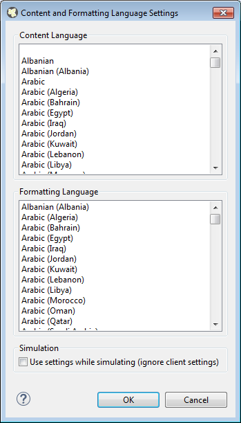
This dialog allows to edit the content language and the formatting language. The language settings are used at design time for displaying the Rich Dialogs in the Rich Dialog Editor. If option Use settings while simulating is checked the settings are also used while simulating.
The following language settings can be configured:
- Content Language
-
The content language is used to select the values of content objects.
- Formatting Language
-
The formatting language is used when Objects are formatted using the
format()method. - Use settings while simulating
-
If checked then the content and the formatting language settings will be used while simulating. If not checked then the settings of the client OS (for RIA) or the browser settings (for HTML) will be used.
To get or set the content or formatting language in IvyScript use
ivy.session.contentLocale respectively
ivy.session.formattingLocale.
Find out more about Axon.ivy's scripting language here.
A breakpoint is a marker that tells the simulation engine to pause the execution. It is then possible to inspect the execution history, to view the values of internal variables and evaluate user defined expressions without being interfered by the running execution. The execution must be resumed by the user explicitly over the functionality of the Debug View. You can see a list of your breakpoints and edit them in the Breakpoint View.
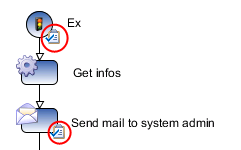
A process element breakpoint is a breakpoint that can be set on a process element. The execution of the process will be interrupted before the process element is executed.
Add / Remove a breakpoint
You can add process element breakpoints in a Process editor or User Dialog Logic editor window by using the popup menu. Right-click on the process step on which you intend to set the breakpoint and go to the Breakpoint sub-menu.
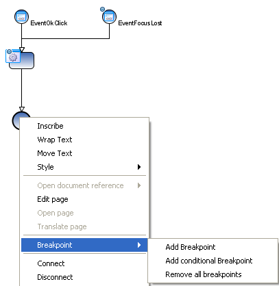
Adding a conditional breakpoint allows you
to define an expression in a input box which must evaluate to true in order to
suspend the execution. In the expression you have access to the in
variable and all other variables in the context of the process step. As you can
see in the figure above, process element breakpoints are visualized in the
Process editor as a small filled dot at the border of the process step  .
.
A data class attribute value change breakpoint is a breakpoint that can be set on a data
class attribute. The execution of the process will be interrupted before the
value of the process data attribute is changed. Data class attribute value
change breakpoints can be added or removed in the Data Class Editor or the Entity Class Editor. The current available variables and the current
debug context is available in the Variables View. The old and new value of the debugging field is
displayed in the variable debug.
Note
The breakpoint only breaks if the value of an attribute is changed by an
IvyScript write attribute operation (e.g.
in.data.myField="Hello"). If the attribute is changed by a
setter method then the breakpoint will not break (e.g.
in.data.setMyField("Hello")).
The debugger provides a set of views and features to inspect the execution (including its history) of your processes and User Dialogs. Akin to a debugger in an Integrated Development Environment (IDE) such as Eclipse, NetBeans or VisualStudio it is possible to set breakpoints to pause an execution, to iterate through executions step-by-step and to examine the history and the current state of the execution in depth.
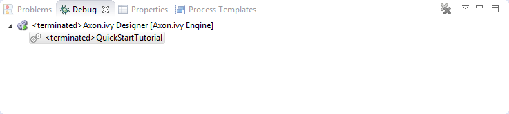
The Debug view shows in a tree per open project all the currently handled requests i.e. all processes under execution in the simulation engine.
For each request to the engine the current state (i.e. the currently executed process step) are shown and can be manipulated individually with the following buttons on the toolbar:

- Resume
-
Resumes the execution of the selected process/request until the end of the process to the next breakpoint
- Terminate
-
Terminates the execution of the selected process/request
- Step Into
-
This can be used to step into a (callable) process element. The current step is executed and then execution is suspended on the next step again.
- Step Over
-
This can be used to step over a (callable) process element. The current step is executed and then execution is suspended on the next step in the current process.
- Step Out
-
This can be used to step out of the current process, the execution is suspended again on the caller process element.
If you select a stack element then the process editor shows the process element that is executed at this stack element. Moreover, the Variable view will display the current values of the process data at the process element of the selected stack element.
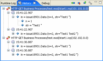
In this view you see the values of your process data (the in
variable) during all runs of the currently selected process element in the process
editor. The topmost tree entry shows the data of the first execution of the selected
element during the first request whereas the entry at the bottom corresponds to the
most current execution.
The following buttons on the toolbar can be used to navigate to process elements and to configure the history:
- Go to process element (
 )
) -
Marks the process element in the process editor whose history is currently displayed.
- Go to next process element (
 )
) -
Shows the history of the next process element.
- Go to previous process element (
 )
) -
Shows the history of the previous process element.
- History view preferences (
 )
) -
Opens the preference page with the settings for the history.
Note
In case of memory shortage during simulation or due to history settings process data snapshots may be discarded. This is indicated by the message "history data no longer available".
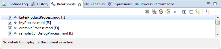
This view lists all the breakpoint which are currently set and offers some functionality to edit and filter single breakpoints.
You can configure and control the View with the toolbar and menu:
- Remove Breakpoints (

 )
) -
You can remove either the selected process(es) or all processes.
- Show Breakpoints Supported by Selected Target
(
 )
) -
Shows only the breakpoints in the list which are included in the process start under execution.
- Go to File for Breakpoint (
 )
) -
Opens an editor with the file containing the breakpoint or sets the focus on the corresponding editor window.
- Skip all Breakpoints (
 )
) -
If set, all breakpoints are skipped.
Tip
This is helpful when you need to debug only some executions of a process steps. You can skip the breakpoints at the beginning and switch this button off, when the execution reaches the part you are interested in.
- Expand All / Collapse All (

 )
) -
If you have grouped the breakpoints together, you can quickly expand or collapse the whole tree
- Link with Debug View (
 )
) -
Links this view together with the Debug View.
- Add Java Exception Breakpoint (
 )
) -
Adds a breakpoint for a type of Java Exceptions, which will be used whenever this Java Exception is thrown throughout the execution.
Warning
Use this feature only if you are familiar with the Java programming language and its exception handling mechanism
- Toolbar Menu (
 )
) -
Here you can group the breakpoints according to some categories, select whether you want to restrict the view on a specific working set and set whether you want to see fully qualified names for breakpoints in Java code.
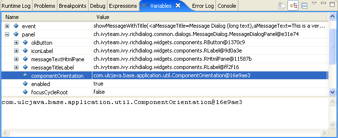
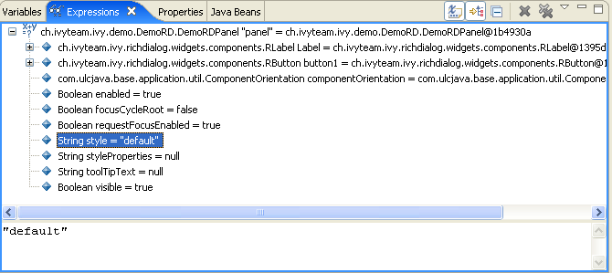
This view shows a list of all variable in the context (or scope) of the currently
executed process step. You are able to examine the structure, the types and the
values of variables and it is even possible to change the values of variables which
have a simple data type (such as String, Number,
Boolean, Time, Date or
DateTime). The view is divided into a variable tree showing the
structure, value and type of each variable (including its members) and a detail pane
that displays the values for deeper examination.
- Collapse All (
 )
) -
Collapse the whole variable tree to its root items.
- Toolbar Menu ()
-
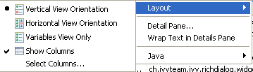
- Layout
-
You can switch on and off the detail pane, set its orientation (vertical or horizontal) and set whether and which columns should be displayed.
- Detail pane
-
Setting for the size of the buffer for the detail pane, the higher the longer values you can examine (e.g. very long strings) but the more memory you use.
- Wrap Text in Details Pane
-
Wrap text in details pane when it does not fit in the available space
- Popup Menu
-
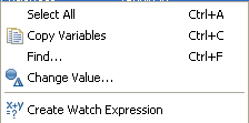
- Select All
-
Selects all elements in the list.
- Copy Variables
-
Copies all selected variables into the clipboard (e.g. for use in the Expressions view).
- Find ...
-
Allows to find a specific variable with a filter string.
- Change Value ...
-
The values of primitive Java data types may be changed here.
- Create Watch Expression
-
Creates a new expression in the Expressions View.
Warning
Changing the value may cause exceptions or introduce undesired side effects with very weird behaviour in the continuation of the execution. Please use this feature with precaution!
In this view you can define expressions, evaluate them and examine their values (similar to the Variables view). In the expression you can use all valid IvyScript operators and language elements and at a certain point of time, only variables which are in the scope of the currently executed process step can be evaluated.
- Show Type Names (
 )
) -
Shows the type names of the variables in the front of the variable.
- Collapse All ()
-
Collapse the whole expression tree to its root items.
- Remove Selected Expressions / Remove All Expressions
(
 )
) -
You can remove either the selected or all expressions.
- Toolbar Menu
()
-
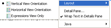
- Layout
-
You can switch on and off the detail pane, set its orientation (vertical or horizontal).
- Detail pane
-
Setting for the size of the buffer for the detail pane, the higher the longer values you can examine (e.g. very long strings) but the more memory you use.
- Wrap Text in Details Pane
-
Wrap text in details pane when it does not fit in the available space.
- Popup Menu
-
- Select All
-
Selects all elements in the list.
- Copy Expressions
-
Copies all selected expressions and their state into the clipboard.
- Find ...
-
Allows to find a specific variable with a filter string.
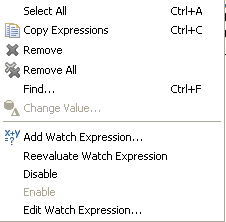
- Add Watch Expression ...
-
Adds a watch expression into the expression view.
- Reevaluate Watch Expression
-
Computes the current value of the expression (e.g. if expression reads data which was manipulated by concurrent threads).
- Disable / Enable
-
Disables or enables the automatic evaluation of expressions when changes occur.
- Edit Watch Expression ...
-
Edits the selected watch expression.
This section explains the Runtime Log view, and how it works.
The Runtime Log view displays a list of events. This events occur during the simulation. When you start the Axon.ivy process engine, this log view is opened by default and all entries are cleared.
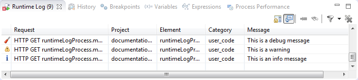
Window > Show View > Runtime Log
Window > Show View > Other ... > Other... > Axon.ivy > Runtime Log
The following columns are displayed in the Runtime Log view:
- First narrow column without name
-
In this column an icon is displayed that symbolizes the type of logged event (info / warning / error message)
- Request
-
The request (HTTP, ULC, etc. with its ID) is displayed in which the log message occurred.
- Project
-
The name of the project the log event was logged in.
- Element
-
The identifier of the process element which logged the event.
- Category
-
The log category refers to the Axon.ivy part which has logged the event (e.g. user_code: ivyScript by user; rich_dialog: at execution of RD; process: log from/during process model execution).
- Message
-
The event message is displayed here.
When you double click on a log entry, a detail window will appear.
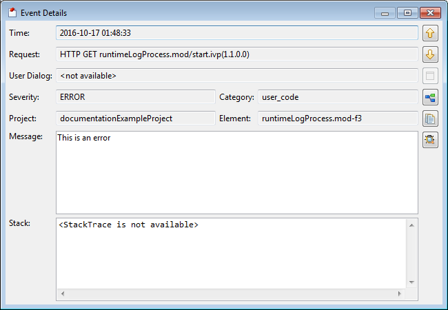
The following fields are displayed in this window:
- Time
-
Time, when the event was logged.
- Request
-
The request (HTTP, ULC, etc. with its ID) in which the log message occurred.
- Rich Dialog
-
The Rich Dialog in which context the event was logged.
Tip
You can jump to this rich dialog using the Goto Rich Dialog button on the right left hand side
- Severity
-
Shows how serious the logged event is (debug, info, warning, or error).
- Project
-
The name of the project the log event was logged.
- Category
-
The log category refers to the Axon.ivy part which has logged the event (e.g. user_code: ivyScript by user; rich_dialog: at execution of RD; process: log from/during process model execution).
- Element
-
The identifier of the process element which logged the event.
- Message
-
The log message is displayed here.
- Stack
-
If an exception was logged with the event, and it contains a stack trace (calling hierarchy), then it is displayed here.
On the right hand side the following buttons are located:
 Previous event
-
Clicking on this button will open the previous event of the logged events list.
 Next event
-
Clicking on this button will open the next event of the logged events list.
-
 Goto rich dialog
 -
This button is available only if the log event contains Rich Dialog information. Clicking on this button opens a new editor showing the Rich Dialog which that has logged the event.
-
 Goto process element
 -
If you click on this button a process is opened and the process element that has logged the event is selected.
-
 Copy event details to clipboard
 -
If you click on this button all log event information are copied to clipboard.
-
 Save Error Report
 -
If you click on this button an error report that contains information about the error, the designer machine and the current state of the Axon.ivy Designer.
This chapter describes how you can log to the runtime log.
Open any process elements that contain IvyScript (like: Step, Web Service, etc.) and type a script like the one you find in the figure below:
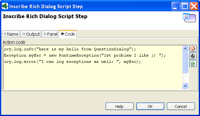
Find out more about Axon.ivy scripting language here.
The Process Performance View displays process performance statistics. This allows to analyse the performance and to detect long running and performance intensive process elements and processes. The view contains detailed information of each executed process element.
Note
On the Axon.ivy Engine there is the possibility to dump out performance statistics to a comma separated value file (*.csv). Check the Engine Guide for more information: Monitoring > Process Element Performance Statistic and Analysis
All time values are in milliseconds. The execution of some process elements are separated in two categories internal and external.
- Internal Category
-
The internal category is used for the execution time in the process engine itself without the external execution.
- External Category
-
The external category is used for execution time in external systems. In the table below the process elements are listed which use the external category.
Process Element Internal Category External Category Database Step Parameter-mapping, caching, output-mapping and ivyScript execution. The execution of the SQL statement on the database server. Web Service Call Step Parameter-mapping, caching, output-mapping and ivyScript execution. The execution of the Web Service on the web server. E-Mail Step Parameter-mapping The interaction with the Mail-Server. Program Interface The execution of the defined Java-Class. Table 2.4. Process elements with usage of external category
For each executed process element one entry in the view is created. See the table below which information is available.
| Name | Description |
|---|---|
| Entry ID | Entry ID, useful to order the entries by its execution |
| Process Path | The path to the process. |
| Element ID | The identifier of the process element. |
| Element Name | The first line of the process element name (display name). |
| Element Type | The type of the process element. |
| Total Time | Total time [ms] of internal and external execution. |
| Int. Executions | Total internal executions of the process element. |
| Total Int. Time | Total internal time [ms] of process engine executions. |
| Min. Int. Time | Minimum internal process engine execution time [ms]. |
| Avg. Int. Time | Average internal process engine execution time [ms]. |
| Max. Int. Time | Maximum internal process engine execution time [ms]. |
| Ext. Executions | Total external execution count. |
| Total Ext. Time | Total external execution time [ms]. |
| Min. Ext. Time | Minimum external execution time [ms]. |
| Avg. Ext. Time | Average external execution time [ms]. |
| Max. Ext. Time | Maximum external execution time [ms]. |
Table 2.5. Column Description
Case Maps can be used to split a long running process into multiple short running processes. See: Adaptive Case Management: Regaining the big picture.
The Case Map controls which processes are executed automatically in which order and which processes can be started manually by users.
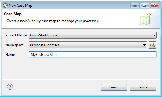
- Project Name
-
Choose the project in which you want to create a new Case Map.
- Namespace
-
Select a process group where the new Case Map will be inserted. Select the
<default>process group to create a Case Map directly below the project's processes folder. You can click on the group folder button to open the New Process Group Wizard, if you want to create a new group "on the fly". The process groups are listed relative to the project's processes folder. - Name
-
Enter the name of the Case Map that you want to create.
The Case map editor is the editor that is shown when you open a case map in the designer. Use it to create and edit Case Maps. At first you typically want to name your case map and add new stages by clicking on the plus (+) symbol.
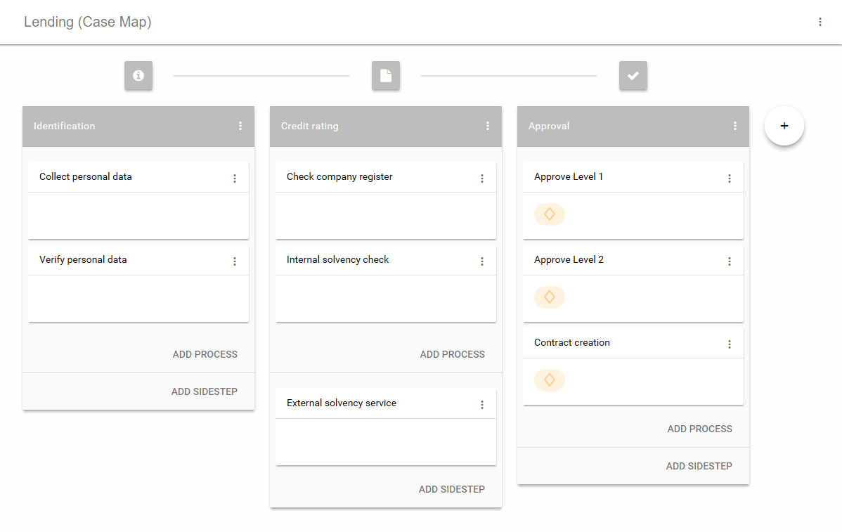
A case map is divided into stages. Each stage defines a certain phase in the life of a business process. A stage is a container for multiples processes that belong to each other in a logical order. Within a stage the processes are executed from top to bottom. If the last process of a stage has finished the execution continues on the stage to the right. Besides processes a stage can also contain Sidesteps, that are valid in the current stage. The actual stage of a Business Case is also displayed in the Workflow UI with it's name and icon.
A business process can programmatically switch to another stage by using the
case map API (ivy.casemap).
The position of a Stage in a case map can be changed via the menu on the stage.
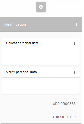
A process in the Case Map references to a process start of an Axon.ivy process. If the business process enters a stage, the first process, which entry condition evaluates to true, will be started.
Processes and Sidesteps can be rearranged around by drag and drop.
Preconditions can be set on a process and define whether a process should be skipped. The precondition on the first process in the case map is not evaluated. If a precondition is not met, the execution continues on the next process. For script features see “Case Map scripting”

Sidesteps are optionally executable processes. Sidesteps like processes belong to a stage. They can be started at any time manually during the ongoing business process. A typical Sidestep could be a process which is used to involve a supervisor to ask for clarification.
Decides whether that Sidestep can be currently started or not. For script features see “Case Map scripting”
Scripts within a Case Map can be written in ivyScript.
A simple Process Precondition could be implemented as follows:
businessCase.getCreatorUserName().equals("Bruno") && creditDossier.needsApproval
Within Case Map scripts the running Business Case is always accessible trough
the variable businessCase.
Any class that is annotated with @BusinessCaseData is accessible
by its simple name (e.g. if the full-qualified name of the class is
com.axonivy.CreditDossier the simple name is:
creditDossier). The variable value will be loaded from the
Business Data Repository.
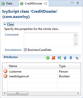
The execution of a Case Map can be followed in the Case Map Editor. As known from the BPM processes the currently executing and already executed elements in the Case Map will be marked. It uses the simulation settings known from the BPM processes.
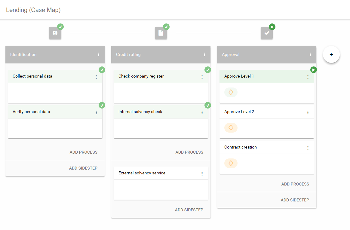
The Case Map provides the ability to display different process metrics of a Case Map in an early version. The monitoring can be enabled via the Case Map menu on the right-hand site. Currently the Case Map statistics only displays the metrics of the actual linked process, metrics of other processes that might have been started from this process are not considered.
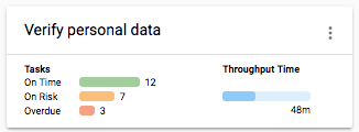
The tasks statistics are based on the expiration dates of the Case Map tasks. Therefore, the task count is only based on tasks with an expiration date. The tasks are divided into following three categories:
- On time
-
Considers the average throughput time to calculate if the tasks are on time. A task is considered on time when the expiry date of the task is more than half of the average throughput time away from the current time.
- On risk
-
Considers the average throughput time to calculate if the tasks are on risk. A task is considered on risk when the expiry date of the task is the half of the average throughput time away from the current time.
- Overdue
-
The task count of expired tasks.
The execution of a process in a Case Map is the same as when it is executed as a standalone process. For each started instance it will create a task and a case. You can configure the created case and task by using the Case and Task tab on the Request Start inscription mask.
By default the responsible role that can work on the created task is the one
configured on the Request tab of the Request Start. If the
Request Start is
triggerable then also the information on the Trigger tab is considered and the task
is assigned to the responsible role or user configured on this tab. To automatically
execute a process, configure the Request Start to be
triggerable and set the responsible role to SYSTEM.
When a stage change happens the Case Map does not cancel tasks thats were started
in the stage before the switching happened. This is mainly important if the stage
switch was performed programmatically using the ivy.casemap API. The
process developer should consider to change the state (e.g. destroy) of existing
tasks manually before switching to another stage change.
This chapter provides detailed explanations for the usage and configuration of all process element, for both business processes and Rich Dialog logic.
Axon.ivy provides a lot of useful process elements that can be used to define processes and the Rich Dialog Logic. These elements reside in the palette on the right edge of the Process editor and of the Rich Dialog editor. You can drag and drop the elements on the editor to use them in a specific process flow. You then can connect two elements by clicking on the source element, let the moused button pressed down, move the mouse cursor to the target element and finally release the mouse button. Reconnecting or removal is only possible by using the corresponding entries in the popup menu.
Every process element can be configured with its inscription mask. Open this mask by double-clicking on the element, use the popup-menu or press the i-key whenever the element is selected. The inscription mask is divided into multiple tabs and the order of the tabs indicates the sequence of processing. For example in the figure below, the Output mapping (the second tab in the middle) is performed before the code in the third tab is executed.
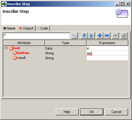
The icons on the tab indicate their state:
-
 the tab is empty
 -
 the tab has been changed by the user (default assignments are
not considered as user entries)
the tab has been changed by the user (default assignments are
not considered as user entries) -
 the tab contains errors
This section describes the most common tabs that are used on more than one element inscription mask.
This tab is included in the inscription mask of all process elements and contains the name and a description of the element.
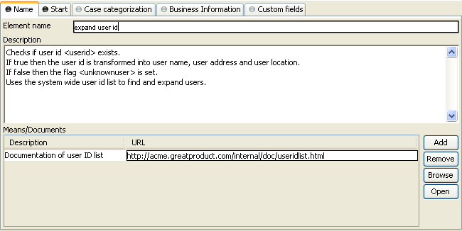
- Element Name
-
Name of the element in the process.
The name will be displayed in the process editor. Various font format options can be chosen on the popup menu of selected text.
Tip
Give each element a name, always. This increases the overview and simplifies the exchange of models between you and your colleagues. If you work in a team, the use of naming conventions are strongly recommended.
- Description
-
Describes the function of the element.
This text appears as tool tip in the process editor whenever the mouse stays over the element.
- Means/Documents
-
A list with references to additional stuff that is related to this process step, i.e. documentation, templates, example forms and many more.
Tip
In generated HTML reports, a link is inserted for these document references.

On this tab you can set all values in the output Data Class. By default the output variable is mapped directly to the input variable, but the user can overwrite either the assignment of the whole output Data Class or only of single members thereof.
Note
In Axon.ivy input and output of process or Rich Dialog logic elements are always set to the corresponding data class, i.e. in a Rich Dialog logic element it is the Rich Dialog Data Class and in a process element it is the project Data Class (or the one which was assigned to the process).
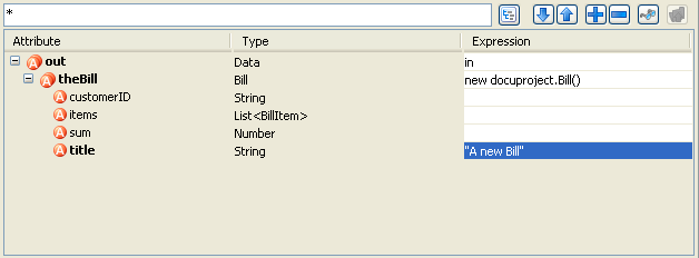
- Filter Box / Toolbar
-
In the upper part you can set a string based filter with wild cards in the text box, set a filter to only show rows with an assigned value (
 ), move between the rows with an assigned
value
), move between the rows with an assigned
value  , expand/collapse the list
 and set the visibility level
(
and set the visibility level
( )
) - Output Tree
-
Here you can see the whole structure of the output variable including each of its members with the assigned values/expressions. You may use the Attribute Browser and the Function Browser to construct the expressions.
The code tab is part of almost each inscription mask and allows the user to define the semantics (behaviour) of the corresponding process element with the built-in Axon.ivy scripting language.
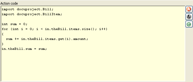
- Code Editor
-
You can write IvyScript code snippets in the part with yellow background. The editor supports code completion and error highlighting. If the background color changes to red, the code contains an error.
Tip
For more information about IvyScript, see IvyScript
- Attribute Browser
-
Here you have access to the local process data in the scope of the element such as the
in- andout-variables, the Rich Dialogpanel(if this is inside the Rich Dialog logic) and other parameters. Click here for more information. - Function Browser
-
Here you have access to some of the most important mathematical functions and to the whole environment of the process such as the request and response properties, the application the process belongs to and many more. Click here for more information.
- Data Class Browser
-
Here you have access to all data classes in the scope of the process element. This includes the built-in Ivy data types such as
String,Number,DateTimeor evenList. Click here for more information.
Here it is possible to access and manipulate the Rich Dialog panel and its members.
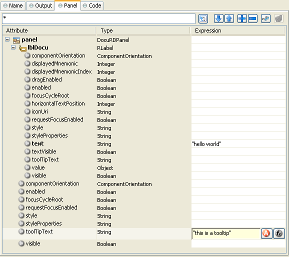
- Filter Box / Toolbar
-
In the upper part you can filter the widgets and attributes by name using wild cards in the text box, set a filter to display only rows with an assigned value (
), move between rows with an assigned
value, expand/collapse the list
and set the visibility level
(). - Panel Tree
-
In the tree you can expand the whole panel hierarchy and manipulate the values of its members.
Process steps that basically encapsulate a read access to master data (data that is changed very rarely) load their data each and every time they are executed even though this is not necessary. With data caches you can first store the values of such steps into a cache in the memory and later read it much faster from the cache the next time you encounter the same step.
Cache entries depend from the active environment and are always bound to their scope - either the current user session or to the running application. Furthermore, they are arranged into groups to make the manipulation for similar entries easier. Cache entries and groups are bound to the life cycle of their scope.
Both groups and entries can be invalidated after a configurable period of time, at a specific time of the day or on request.
For more information about this topic, please refer to the Data Caching section.
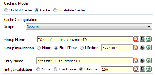
The tab data cache is included in the inscription mask of the Web Service and the DB element. It features the following entries:
- Do Not Cache
-
Does not use the data caching mechanism at all, the element is executed normally. This is the default setting for all elements.
- Cache
-
Uses the data caching mechanism to execute the element. First the whole data cache is searched for the entry described below in the Info part. If found, the cached value is returned and the execution of the element ends. If not found, the element is executed normally, but in the end the result is stored in the data cache.
- Invalidate Cache
-
Invalidates the data cache entry specified in the Info part. Use this when your element performs a write operation that changes data which is cached. The step is executed normally, but in addition the specified data cache entry is invalidated.
- Scope
-
Either Session, Environment or Application. With Session scope, the cache entry is linked to the currently logged in user (i.e. is specific for each user and is invalidated when the user logs out). With Environment scope the cache entry is linked to current environment. With Application scope, the cache entry is linked to the Application.
Warning
Use caches sparingly and with precaution! If you cache results from process steps with huge results (in terms of memory usage), your memory can fill up very fast. This can even get worse if you frequently use the Session scope and the result is cached multiple times (once for each session i.e. user)
- Group Name
-
The name for the group to which the entry will be added. The group resides under the scope, so it is possible to have two groups with the same name, one for both scopes. Use always the same group name if you want to put multiple data cache entries in different process steps into the same group.
- Group Invalidation
-
You can choose between no invalidation, an invalidation at a fixed time or a lifetime based invalidation. If you set a fixed time, then the cache is invalidated once a day at the chosen time. For a lifetime based invalidation, you can set for how many seconds the cache group should be valid after it's initial creation. After the expiry of the lifetime the whole group and all entries in the group are invalidated.
- Entry Name
-
The name for the entry. This name must be unique within the group but you are allowed to have multiple entries with the same name in different groups. Use always the same entry names (as well for the group) if you want to use the same data cache entry in multiple process steps.
- Entry Invalidation
-
You can choose between no invalidation, an invalidation at a fixed time or a lifetime based invalidation. If you set a fixed time, then the cache entry is invalidated once a day at the chosen time. For a lifetime based invalidation, you can set for how many seconds the cache entry should be valid after its initial creation. After the expiry of the lifetime the entry is invalidated.
 The Start (Request Start)
element is located in the Event & Gateway drawer of the Process
editor palette.
The Start (Request Start)
element is located in the Event & Gateway drawer of the Process
editor palette.
The Request Start element is the start point of a workflow. A workflow contains one case and at least one task. Each start of a Request Start creates a new case and task.
There are two ways to start a new workflow:
-
Request
Most workflows are started with a HTTP request. The start Links can be found on the Process Start Overview HTML page and can be placed on an external web sites or as shortcut on the desktop.
The public API provides also a ways to get a list of all request starts for custom start lists or own implemented start mechanism:
ivy.session.getStartableProcessStarts()The HTTP request start can be configured on the Request Tab
-
Triggered
The second way to start a new workflow is by a Trigger Element. On call, it creates a new case and a new task to the Request Start with the defined configurations (and parameters). This offers a simple way to create several workflows inside a other workflow.
The trigger start can be configured on the Trigger Tab
These two start types could be enabled or disabled separately.
This tab is included in the mask of all process elements and contains the name and a description of the element. See Name Tab for a more detailed description.
The start tab defines the name and the parameters to start the process. The signature is a definition of the name with the parameter types and its order. Elements like Call Sub or Trigger referenced to this signature.
- Signature
-
Displays the current signature. Namespaces of the parameter types are not displayed, but they are still a part of the signature, that identifies a start uniquely.
- Name
-
Signature name is case sensitive and can only contain letters (a-Z), numbers (0-9) and underscores (_).
- Definition of input parameters
-
Defines the input parameter of the interface. The type of the parameters and its order is used for the signature. Changing the order or the type, changes also the signature. All referenced elements has to be updated.
- Mapping of input parameters to process data
-
This section is to mapping the incoming parameters to the internal process data. The parameters are available as fields on a param variable.
Note
The reason you have to assign the incoming parameters to local data is to keep the internal implementation independent from the signature declaration. The mapping of parameters serves as a flexible adapter mechanism. The implementation can be changed (rename data, use different data types, etc.) without changing the signature. That way none of the clients of the Process have to be changed as long as only the implementation changes and the signature stays.
Note
Only the defined input parameter on the signature can be assigned to the process data. The internal process data is hidden and encapsulated from the environment. This makes it impossible to inject unintended, insecure data into the process data.
Note
To submit parameters with a HTTP-Request you can simply add them to the URL.
If you have for example defined a parameter named myParameter in the signature, append
?myParameter=hallo to the URL to pass the value hallo to the parameter myParameter.
If you want to pass values for multiple parameters the following parameter
need an & instead of an ?. For example:
?param1=value1¶m2=value2¶m3=value3
Tip
You may already specify the type of the parameter here by adding a colon ':' to the parameter name, followed by desired type (e.g. myDateParameter:Date).
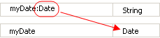
This tab contains the configuration for the HTTP-Request start. Name and description which is displayed on the start list. The required permissions to start the process, and the workflow mode.
- Enablement
-
If Yes, this start can be started with a HTTP-request/ -link is checked, the HTTP request mechanism for this start element is enabled. Otherwise it is not possible to start the request start with a HTTP request.
- Start Link HREF (.ivp)
-
Contains the name of the Process Start link. Notice that this link always has to end on .ivp. This is required for proper association of the request by the web server. Important: this name has to be unique within its process.
- Show in Start List
-
Defines whether this process should appear in the start list of the Process Start Overview HTML page or not.
- Name
-
Defines the display name of the process start in the start list.
- Description
-
Sets a description of the process start. It is displayed in the start list of the Process Start Overview HTML page.
- Responsible Role
-
Users which want to start the process must be assigned to this role.
Tip
In the Designer you can create test users and assign them the role to test this element, on the Axon.ivy Engine you must create the real users separately (roles can be imported from the designer).
- Only Wf Users
-
Limits the process to users that are registered in the Axon.ivy Engine as users. If the box has not been checked also anonymous users (which own the Everybody role by default) may start the process.
- Role Violation error
-
The selected exception element is thrown when the user lacks the required role. The error can be handled by a catching “Error Start”.
- Persist task on creation
-
If selected, the case and task are directly persistent on request start. The Case state will be
RUNNINGinstantly (skipping the stateCREATED) and the Task state will beRESUMED(skipping the stateCREATED). The task could also be reset after the Start Request and the next Task Switch or Process End.This option only available when the option Only WF User is activated.
Note
If the option is selected, the task could be reseted in the process (with
task.reset()). This will reset the process data and the current user got the task to his task list.Note
When a session timeout occurs,
task.reset()is called automatically on the task. Thereby the user has the task again in his task list.Tip
Usually only processes including at least one Task Switch element has this option selected. Because per default a new task is in state
CREATEDuntil the task become persisted. If the option is selected, the task get directly into the stateRESUMED. With this behaviour is now possible to distinguish tasks which have a Task Switch element in their process and others without one. This helps to separate tasks in the task overview from workflow starts (with different steps) and simple process starts (which e.g. only outputs some informations).
This tab holds definitions for starting this workflow with a Trigger Element.
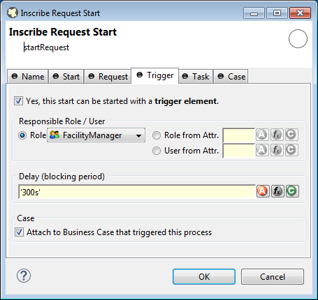
- Enablement
-
If Yes, this start can be started with a trigger element is checked, the trigger mechanism for this start element is enabled. Otherwise it is not possible to choose the Request Start element in a Trigger Element.
Note
When an already related Trigger Element links to a disabled start, this will not prohibit the execution at runtime. An error is logged to the log file and the process starts with its defined configuration.
- Responsible Role / User
-
Defines the role or user required to carry out the task created with the Trigger Element.
Use Role from Attr. or User from Attr., if the role or user must be set dynamically during process execution. For example from a parameter set by the Trigger Element.
Use Role, if you know the responsible role when editing the element.
The role SYSTEM means that no human intervention is required. The system executes the task automatically.
The role CREATOR means that the user who has started the current case is responsible for the task created by the Trigger Element.
- Delay (blocking period)
-
The task can be blocked before a user can work on it. This ivyScript expression defines the Duration the task is blocked.
- Case
-
Define whether the triggered case should be attached to the same “Business Case” as the triggering case.
This tab defines information relevant to the task. Only tasks created with the Trigger Element (see Trigger Tab) will appear in the task list as suspended tasks. Tasks started with a HTTP request (see Request Tab) normally do not appear in the task list.
- Entry in Task List
-
Defines the name and description of the task that appear in the task list of the assigned role or user.
- Priority
-
Here you select the priority of the task. In the task list you can filter the tasks according the priority.
- Expiry
-
An ivyScript expression defines the Duration until the task will expire. If that happens the escalation procedure defined by the following parameters is executed.
-
Exception: Starts an exception process if defined. >> Ignore Exception will not start an exception process.
-
Responsible Role / User after expiry: Defines the Role / User to reassign the task to.
-
Priority after expiry: Defines the new Priority of the task after it has expired.
Note
A task created with a HTTP request (see Request Tab) is executed immediately. Defining Expiry Timeout makes only sense in combination when starting with a Trigger Element (see Trigger Tab)
-
This tab allows to set additional information to categorize the task created. The values set on this tab are only informational and have no effect on how this task is treated by Axon.ivy.
You can set the name of the business calendar that should be used for this task. In the
context of this task ivy.cal will return this business calendar
regardless of what you've set for the case or environment.
For more information about business calendar administration see the engine guide.
For more information about business calendar usage see the Public API of
ch.ivyteam.ivy.application.calendar.IDefaultBusinessCalendar.
On this tab you can configure the Case created by this Start Request. See “Case Tab” in the Task Switch Gateway element.
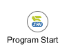 The Program Start element is
located in the Event & Gateway drawer of the process editor
palette.
The Program Start element is
located in the Event & Gateway drawer of the process editor
palette.
The program start element allows to start a process by a trigger from embedded external
Java code. This opens a possibility to integrate an Axon.ivy application into other
applications and systems. The program start element will instantiate a Java class that
must implement the IProcessStartEventBean interface. The Java class can then start
the process by calling the method fireProcessStartEventRequest on the
Axon.ivy runtime engine IProcessStartEventBeanRuntime. The common way to implement a
Start Event Bean is to extend the abstract base class AbstractProcessStartEventBean.The interface also includes an
inner editor class to parametrize the bean. You will find the documentation of the
interfaces and abstract class in the Java Doc of the Axon.ivy Public API.
This tab is included in the mask of all process elements and contains the name and a description of the element. See Name Tab for a more detailed description.
On this tab you define the Java class to execute.
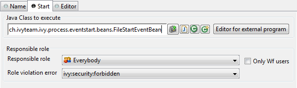
- Java Class to execute
-
Full qualified name of the Java class that implements the
IProcessStartEventBeaninterface. Use the New Bean Class Wizard ( ) to create a new Java source
file with an example implementation of the bean class.
) to create a new Java source
file with an example implementation of the bean class. - Responsible role
-
Defines the role that is required to be able to start a process. The bean will set up an authorised session that calls the
fireProcessStartEventRequest()from theeventRuntimeto trigger a process.
This tab displays the editor, that can be integrated in the external Java bean of the
process element. The editor is implemented as an inner public static class of the Java bean
class and must have the name Editor. Additionally the editor class must
implement the IProcessExtensionConfigurationEditorEx interface. The common way to
implement the editor class is to extend the abstract base class AbstractProcessExtensionConfigurationEditor and to override the
methods createEditorPanelContent, loadUiDataFromConfiguration and
saveUiDataToConfiguration. The method createEditorPanelContent
can be used to build the UI components of the editor. You can add any AWT/Swing component to
the given editorPanel parameter. With the given editorEnvironment
parameter, which is of the type IProcessExtensionConfigurationEditorEnvironment, you can create text
fields that support ivyScript and has smart buttons which provide access to the process
data, environment functions and Java classes.
Here is an example of such an editor:
As you can see, the editor provides you access to any process relevant data, which can be used by your own process elements. For instance, you can easily transfer process data to your legacy system.
The following part shows the implementation of the editor shown above. As mentioned above
Axon.ivy provides the IIvyScriptEditor which represents a text field with ivyScript support
and smart buttons. Inside createEditorPanelContent use the method
createIvyScriptEditor from the editorEnvironment parameter to
create an instance of such an editor. Use the loadUiDataFromConfiguration
method to read the bean configuration and set them to the UI components. Inside this method
you can use the methods getBeanConfiguration or
getBeanConfigurationProperty to read the bean configuration. Use the method
saveUiDataToConfiguration to save the data in the UI components to the bean
configuration. Inside this method you can use the methods setBeanConfiguration
or setBeanConfigurationProperty to save the bean configuration.
  public static class Editor extends AbstractProcessExtensionConfigurationEditor
  {
    private IIvyScriptEditor editorUser;
    private IIvyScriptEditor editorEventTyp;
    private IIvyScriptEditor editorLinkId;
    private IIvyScriptEditor editorFieldValue;

    @Override
    protected void createEditorPanelContent(Container editorPanel,
            IProcessExtensionConfigurationEditorEnvironment editorEnvironment)
    {
      editorPanel.setLayout(new GridLayout(4,2));
      editorUser = editorEnvironment.createIvyScriptEditor(null,null, "String");
      editorEventTyp = editorEnvironment.createIvyScriptEditor(null,null, "String");
      editorLinkId = editorEnvironment.createIvyScriptEditor(null, null, "String");
      editorFieldValue = editorEnvironment.createIvyScriptEditor(null, null);

      editorPanel.add(new JLabel("User"));
      editorPanel.add(editorUser.getComponent());
      editorPanel.add(new JLabel("Event Typ"));
      editorPanel.add(editorEventTyp.getComponent());
      editorPanel.add(new JLabel("Link-Id"));
      editorPanel.add(editorLinkId.getComponent());
      editorPanel.add(new JLabel("Feldwert"));
      editorPanel.add(editorFieldValue.getComponent());
    }

    @Override
    protected void loadUiDataFromConfiguration()
    {
      editorUser.setText(getBeanConfigurationProperty("User"));
      editorEventTyp.setText(getBeanConfigurationProperty("EventTyp"));
      editorLinkId.setText(getBeanConfigurationProperty("LinkId"));
      editorFieldValue.setText(getBeanConfigurationProperty("Feldwert"));
    }

    @Override
    protected boolean saveUiDataToConfiguration()
    {
      setBeanConfigurationProperty("User", editorUser.getText());
      setBeanConfigurationProperty("EventTyp", editorEventTyp.getText());
      setBeanConfigurationProperty("LinkId", editorLinkId.getText());
      setBeanConfigurationProperty("Feldwert", editorFieldValue.getText());
      return true;
    }
  }
At runtime you have to evaluate the IvyScript the user have entered into the ivy script
editors. If you implement for example the AbstractUserProcessExtension class there is a perform method which is
executed at runtime. At this point you want to access the configured data in the editor. The
following code snippet show how you can evaluate the value of an IIvyScriptEditor. If you use the IIvyScriptEditor you only get the value by calling the
executeIvyScript method of the AbstractUserProcessExtension.
  public CompositeObject perform(IRequestId requestId, CompositeObject in,
     IIvyScriptContext context) throws Exception
  {
    IIvyScriptContext ownContext;
    CompositeObject out;
    out = in.clone();
    ownContext = createOwnContext(context);

    String eventtyp = "";
    String linkId = "";
    String fieldValue = "";
    String user= "";

    user = (String)executeIvyScript(ownContext, getConfigurationProperty("User"));
    eventtyp = (String)executeIvyScript(ownContext, getConfigurationProperty("Event Typ"));
    linkId = (String)executeIvyScript(ownContext, getConfigurationProperty("Link-Id"));
    fieldValue = (String)executeIvyScript(ownContext, getConfigurationProperty("Feldwert"));

    // add your call here

    return out;
  }
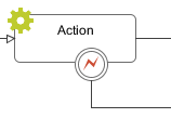 The Error Boundary Event can be attached to any
activity by using its context menu.
The Error Boundary Event can be attached to any
activity by using its context menu.
The execution of an activity can be aborted with an error. The execution is then redirected to this Error Boundary Event element and continued from there. Within the follow up flow the process can handle the error by executing compensation steps or user activities.
See the Error Handling concept for sample use cases.
This tab is included in the mask of all process elements and contains the name and a description of the element. See Name Tab for a more detailed description.
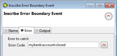
On this tab you can configure the output of the element (i.e. the data that leaves the element). See Output Tab for a more detailed description.
Note
Additionally to the regular variables of the Output Tab you have the following variable available:
- error
-
References the occurred
BpmError. Gives access to the occurred Error Code, Cause and CallStack.
 The Error Start Event element is located in the
Event & Gateway drawer of the process editor palette.
The Error Start Event element is located in the
Event & Gateway drawer of the process editor palette.
The execution of a process element can be aborted with an error. The execution can continue at an Error Start Event which handles the occurred error. Within the follow up flow the process can handle the error by executing compensation steps or user activities.
See the Error Handling concept for sample use cases.
This tab is included in the mask of all process elements and contains the name and a description of the element. See Name Tab for a more detailed description.
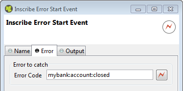
On this tab you can configure the output of the element (i.e. the data that leaves the element). See Output Tab for a more detailed description.
Note
Additionally to the regular variables of the Output Tab you have the following variable available:
- error
-
References the occurred
BpmError. Gives access to the occurred Error Code, Cause and CallStack.
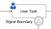 The Signal Boundary Event can be attached to a User Task by using its context menu.
A Signal Boundary Event destroys an open task of a user if a signal code is received that matches the inscribed pattern.
See the Signal concept for sample use cases.
This tab is included in the mask of all process elements and contains the name and a description of the element. See Name Tab for a more detailed description.
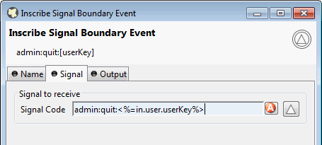
On this tab you can configure the output of the element (i.e. the data that leaves the element). See Output Tab for a more detailed description.
Note
Additionally to the regular variables of the Output Tab you have the following variable available:
- signal
-
Gives access to the signal event.
 The Signal Start Event element is located in the
Event & Gateway drawer of the process editor palette.
The Signal Start Event element is located in the
Event & Gateway drawer of the process editor palette.
The Signal Start Event listens to a signal. It starts a new process when a signal with a matching signal code has been received.
See the Signal concept for sample use cases.
This tab is included in the mask of all process elements and contains the name and a description of the element. See Name Tab for a more detailed description.
On this tab you configure the Signal Code that the Signal Start Event will listen to.
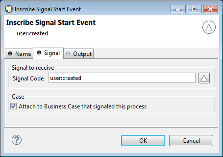
- Case
-
Define whether the triggered case should be attached to the same “Business Case” as the signaling case.
On this tab you can configure the output of the element (i.e. the data that leaves the element). See Output Tab for a more detailed description.
Note
Additionally to the regular variables of the Output Tab you have the following variable available:
- signal
-
Gives access to the signal event.
 The Alternative Gateway element is located in the Event &
Gateway drawer of the process editor palette.
The Alternative Gateway element is located in the Event &
Gateway drawer of the process editor palette.
An Alternative is a switch that connects the process flow to one of the exits of the element depending on the evaluation of the exit conditions. So, you can use this element to perform business rules (in the form of if - else if - else decisions) or to build loops in the process flow.
This tab is included in the mask of all process elements and contains the name and a description of the element. See Name Tab for a more detailed description.
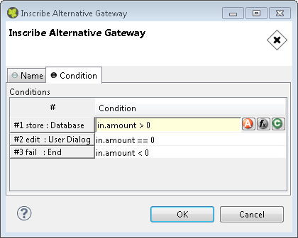
- Conditions
-
Each row in this table is assigned to an exit of this element. In the column Condition boolean expressions must be entered. The conditions are evaluated from the top to the bottom and the exit of the first one that evaluates to true is chosen, i.e. the process will proceed by the path connected to this exit.
 The Split Gateway element is located in the Event &
Gateway drawer of the process editor palette.
The Split Gateway element is located in the Event &
Gateway drawer of the process editor palette.
This allows you to model parallel process paths. The element may split one process path into a number of paths that are executed concurrently. The input process data is copied to all the parallel executions but can be manipulated in each path individually.
Note
Use this element always together with the Join element.
Tip
Use the split and the join element to execute parallel database or web service requests.
Warning
Do not put any user interaction (Rich Dialog, HTML Page) or task element within a slitted process path.
This tab is included in the mask of all process elements and contains the name and a description of the element. See Name Tab for a more detailed description.
On this tab you can configure the output of the element (i.e. the data that leaves the element). See Output Tab for a more detailed description.
Note
For each outgoing connection you have a separate outX object available which carries the data of the Xth output. Hover with the mouse over the outgoing connections of the element to see which output connection corresponds to which variable.
On this tab you can execute any IvyScript, e.g. define output data of this element. See code tab for a more detailed description.
Tip
The entered code will be executed after the execution of the output tab. Although this may seem a bit counter-intuitive at first, you should simply regard the code tab as an alternative way of defining output data. The general recommendation is to use the output table to define simple assignments and the code tab if more extensive scripting is needed to calculate data.
 The Join Gateway element is located in the Event &
Gateway drawer of the process editor palette.
The Join Gateway element is located in the Event &
Gateway drawer of the process editor palette.
This element synchronizes and joins a parallel execution of process paths together. The output of each incoming path is copied into the element and can be used to define its output.
Note
This elements waits until all of the parallel incoming process paths have finished and reached this element.
Tip
Use the Split element to create parallel process paths.
This tab is included in the mask of all process elements and contains the name and a description of the element. See Name Tab for a more detailed description.
On this tab you can configure the output of the element (i.e. the data that leaves the element). See Output Tab for a more detailed description.
Note
For each incoming connection you have a separate inX object available which carries the data of the Xth input. Hover with the mouse over the incoming connections of the element to see which input connection corresponds to which variable.
On this tab you can execute any IvyScript, e.g. define output data of this element. See Code Tab for a more detailed description.
Tip
The entered code will be executed after the execution of the output tab. Although this may seem a bit counter-intuitive at first, you should simply regard the code tab as an alternative way of defining output data. The general recommendation is to use the output table to define simple assignments and the code tab if more extensive scripting is needed to calculate data.
 The Task Switch Gateway element is located in the Event &
Gateway drawer of the process editor palette.
The Task Switch Gateway element is located in the Event &
Gateway drawer of the process editor palette.
With the task switch element a process is segmented into tasks. It interrupts the execution of a process and allows another user to proceed. The actual process state is stored in the system database. A role or user is assigned that is able to pick up and start the task.
When the role SYSTEM has been chosen the process is executed by the system, without manual intervention by a user.
Note
If any error occurs during the execution of a task that is executed by the system the task is rolled back and its state set to error. After a certain time the task is resumed and the system tries again to execute it.
The duration until a task with state error is resumed depends on the times the task had failed before (1, 2, 4, 8 minutes, ... up to 23 hours).
This is a default behaviour. To change it consult the documentation of ch.ivyteam.ivy.workflow.SystemTaskFailureBehaviour
Warning
The Task Switch Gateway element can have several input and output arcs and acts as an AND-Gateway. It synchronizes all incoming tasks - it waits until all incoming tasks have been completed.
For each outgoing arc the Task Switch Gateway element creates a parallel task.
Warning
The process state that is stored to the system database contains all process data values that are stored in persistent fields. Values of non persistent fields are not stored to the system database and are therefore not initialized in the process data of the created tasks.
This tab is included in the mask of all process elements and contains the name and a description of the element. See Name Tab for a more detailed description.
On this tab you can configure the output of the element (i.e. the data that leaves the element). See Output Tab for a more detailed description.
Note
For each incoming connection you have a separate inX object available which carries the data of the Xth input. Hover with the mouse over the incoming connections of the element to learn which input connection corresponds to which variable.
This tab defines the parameters for the tasks created by the Task Switch.
Defines the name, the description and category of the task that appear in the task list of the addressed role or user.
Tip
It is recommended practice to define and reference the text from the CMS. Look at the workflow concept for some more information about categorization.
- Responsible Role / User
-
Defines the role or user required to carry out the task.
Use Role from Attr. or User from Attr., if the role or user must be set dynamically during process execution. For example from a process-attribute which holds the name of a role or user.
Use Role, if you know the responsible role when editing the element.
The role SYSTEM means that no human intervention is required. The system executes the task automatically.
The role SELFx (SELF1, SELF2, ...) means that the same user that has finished the task on entry x is responsible for the task.
The role CREATOR means that the user who has started the current case is responsible for the task.
Normally a user interaction ends at a Task Switch element. It will be redirected to the task list or an end page is shown. If Skip tasklist is activated for a task the user interaction may not end at the Task Switch element. It is automatically redirected to this new task marked with Skip tasklist. But only if it is allowed to work on the task and the Task Switch is not waiting for any other tasks to finish.
Only one task of a Task Switch element can activate Skip tasklist.
- Priority
-
Here you select the priority of the task. In the task list you can filter the tasks according the priority.
- Delay
-
The task can be blocked before a user can work on it. This ivyScript expression defines the Duration the task is blocked.
- Expiry
-
An ivyScript expression defines the Duration until the task will expire. If that happens the escalation procedure defined by the following parameters is executed.
-
Exception: Starts an exception process if defined. >> Ignore Exception will not start an exception process.
-
Responsible Role / User after Expiry: Defines the Role / User to reassign the task to.
-
Priority after expiry: Defines the new Priority of the task after it has expired.
Note
If a Delay is defined, the expiry timeout begins after the Delay.
-
Note
A user can be informed by mail if a new task for him was created. This feature is useful for users that only occasionally participate in workflows. On the other hand a user who participate often with the workflow may find daily summary mails useful. User mail notification can be configured on the Axon.ivy Engine in the Engine Administration UI or in the Workflow UI applications (For more information read the chapter User and Roles in the Axon.ivy Engine Guide).
This Tab allows to set additional information for the task created. The values set on this tab are only informational and have no effect on how this task is treated by Axon.ivy.
This Tab allows to set additional information to categorize the task created. The values set on this tab are only informational and have no effect on how this task is treated by Axon.ivy.
You can set the name of the business calendar that should be used for this task.
In the context of this task ivy.cal will return this business calendar
regardless of what you've set for the case.
For more information about business calendar administration see the engine guide.
For more information about business calendar usage see the Public API of
ch.ivyteam.ivy.application.calendar.IDefaultBusinessCalendar.
Every time a process is started a case is created. This tab allows you to define additional information for the cases. The information defined on this tab has no effect how Axon.ivy treats the cases. But they can be accessed through the Public API, which allows you to use them for example to filter the task list.
You can define the name, the description and the catgegory for the corresponding case.
Note
Look at the workflow concept for some more information about categorization.
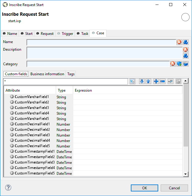
Here you can set the values for at most 5 user defined fields for each of the three data
types String, Number and DateTime. You can reuse
these fields in IvyScript over its API.
Warning
This feature is deprecated. This tab only appears if you activate it in Deprecation Preferences or if there are already values inscribed on this tab. Instead use Business Data to define custom fields, which are searchable.
On this tab it is possible to edit further information about the process such as contact and business data.
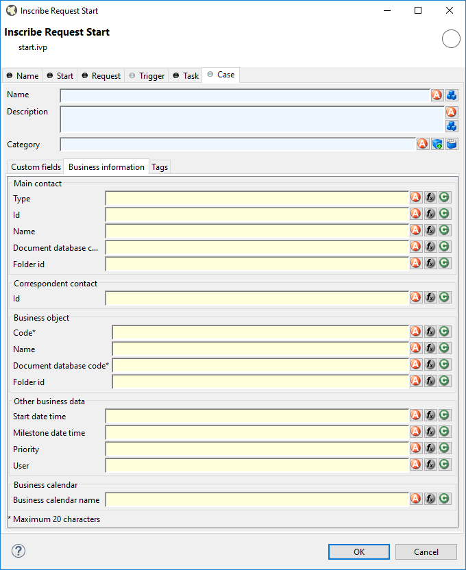
- Main Contact
-
Here you can set the information about the company your process deals with.
- Correspondent Contact
-
Here you can set the information about the contact person in the company your process deals with.
- Business Object
-
Here you can set the information about the business object your process deals with.
- Other
-
You can set here additional information about time constraint and further things.
- Business calendar
You can set the name of the business calendar that should be used for this case. In the context of this case
ivy.calwill return this business calendar instead of the default business calendar. It is also possible to set a business calendar for a task.For more information about business calendar administration see the engine guide.
For more information about business calendar usage see the Public API of
ch.ivyteam.ivy.application.calendar.IDefaultBusinessCalendar.
Warning
This feature is deprecated. This tab only appears if you activate it in Deprecation Preferences or if there are already values inscribed on this tab. Instead use the category field to categorize your cases.
Here you can structure processes in more depth and categorize them into a user-defined
hierarchy. These categorization attributes may be accessed later over an API to filter and
structure the task overview of users. The structure always consists of 4 levels, the
process category, the process, the process type and process sub type, e.g.
myProcessCategory/myProcess/myProcessType/myProcessSubtype.
Tip
Create your specific hierarchy in the CMS so you can ensure its consistent use.
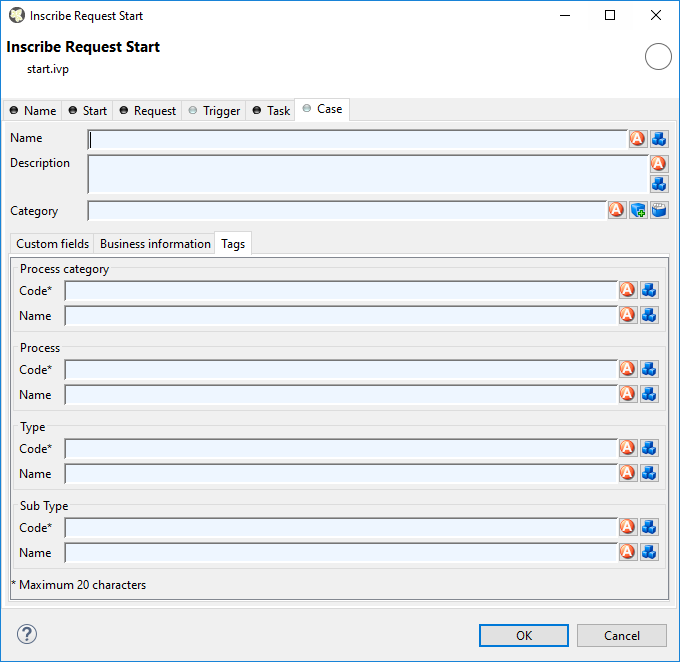
- Process Category
-
Sets the category code and name of the category this process belongs to.
- Process
-
Sets the process code and name.
- Type
-
Sets the process type code and name.
- Sub Type
-
Sets the sub type code and name of this process.
Note
The code is always used for internal reference (caching, searching, sorting and the like) and never shown to the actual user. Therefore, the codes should be unique within its level. The name on the other side is human-readable and always shown to the user when the element is referenced.
This Tab defines the page, which will be displayed in the web browser for each task which ends at this Task Switch Element.
If no page is defined the task list will be shown.
If no task is created because skip task list is enabled (see Task Tab) the case will continue without displaying a page or the task list.
- Dialog Page
-
Pages can be referenced from the content management system or the web content directory. The wizard allows you to create, select or edit pages.
Please refer to Creating and Editing HTML Pages in the HTML chapter for a more thorough explanation of this tab section.
 The Task Switch Event element is located in the Event
& Gateway drawer of the process editor palette.
The Task Switch Event element is located in the Event
& Gateway drawer of the process editor palette.
The Task Switch Event element has quite the same function than the Task Switch Gateway element. The different is, that a Task Switch Event element could only have one input and one output, instead of multiple as the parallel Task Switch Gateway. The usage of this simplified element is to have a more BPMN conform element.
See Task Switch Gateway for a more detailed description.
 The Wait Program Intermediate Event element
is located in the Event & Gateway drawer of the process editor
palette.
The Wait Program Intermediate Event element
is located in the Event & Gateway drawer of the process editor
palette.
This element is one of Axon.ivy facilities to integrate custom-made software, legacy systems, proprietary applications or any other external system through an Axon.ivy Java interface. At an Intermediate Event element the process execution is interrupted and waits for an external event to occur. Technically spoken the current task will be ended and a new system task is created that waits for the intermediate event. If the intermediate event is fired the new task and therefore the process after the intermediate event will be executed.
You provide a listener for the external event by implementing a Java class that
implements the IProcessIntermediateEventBean interface. The Wait Program Intermediate Event
Element instantiates the Java class and can then trigger the intermediate event by
calling the method fireProcessIntermediateEventEx on the Axon.ivy runtime
engine IProcessIntermediateEventBeanRuntime. The common way to implement
an Intermediate Event bean is to extend the abstract base class AbstractProcessIntermediateEventBean. The interface also includes
an inner editor class to parametrize the bean. You will find the documentation of the
interface and the abstract class in the Java Doc of the Axon.ivy Public API.
This tab is included in the mask of all process elements and contains the name and a description of the element. See Name Tab for a more detailed description.
On this tab you define the Java class that the IntermediateEvent should instantiate, the identifier of the event to wait for and the timeout behaviour.
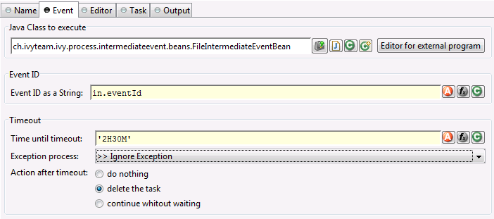
- Java Class to execute
-
Fully qualified name of the Java class that implements the
IProcessIntermediateEventBeaninterface. Use the New Bean Class Wizard () to create a new Java source
file with an example implementation of the bean class. - Event ID
-
Because multiple cases (process instances) can wait on the same intermediate event you must specify which event belongs to which waiting case. Here you specify the identifier of the event the current case should wait for.
Warning
The event identifier as a String must be unique. Do not use a static string like
"myID". A good practice is to integrate the case identifier (ivy.case.getIdentifier()) into the event id. - Timeout
-
Here you can specify a time (Duration) how long the current case should wait for an intermediate event and what should happen if no event has been received after this time. You can optionally start an exception process, delete the waiting task or continue the waiting task without receiving an intermediate event.
This tab displays the editor, that can be integrated in the external Java bean of the
process element. The editor is implemented as an inner public static class of the Java bean
class and must have the name Editor. Additionally the editor class must
implement the IProcessExtensionConfigurationEditorEx interface. The common way to
implement the editor class is to extend the abstract base class AbstractProcessExtensionConfigurationEditor and to override the
methods createEditorPanelContent, loadUiDataFromConfiguration and
saveUiDataToConfiguration. The method createEditorPanelContent
can be used to build the UI components of the editor. You can add any AWT/Swing component to
the given editorPanel parameter. With the given editorEnvironment
parameter, which is of the type IProcessExtensionConfigurationEditorEnvironment, you can create text
fields that support ivyScript and has smart buttons which provide access to the process
data, environment functions and Java classes.
Here is an example of such an editor:
As you can see, the editor provides you access to any process relevant data, which can be used by your own process elements. For instance, you can easily transfer process data to your legacy system.
The following part shows the implementation of the editor shown above. As mentioned above
Axon.ivy provides the IIvyScriptEditor which represents a text field with ivyScript support
and smart buttons. Inside createEditorPanelContent use the method
createIvyScriptEditor from the editorEnvironment parameter to
create an instance of such an editor. Use the loadUiDataFromConfiguration
method to read the bean configuration and set them to the UI components. Inside this method
you can use the methods getBeanConfiguration or
getBeanConfigurationProperty to read the bean configuration. Use the method
saveUiDataToConfiguration to save the data in the UI components to the bean
configuration. Inside this method you can use the methods setBeanConfiguration
or setBeanConfigurationProperty to save the bean configuration.
  public static class Editor extends AbstractProcessExtensionConfigurationEditor
  {
    private IIvyScriptEditor editorUser;
    private IIvyScriptEditor editorEventTyp;
    private IIvyScriptEditor editorLinkId;
    private IIvyScriptEditor editorFieldValue;

    @Override
    protected void createEditorPanelContent(Container editorPanel,
            IProcessExtensionConfigurationEditorEnvironment editorEnvironment)
    {
      editorPanel.setLayout(new GridLayout(4,2));
      editorUser = editorEnvironment.createIvyScriptEditor(null,null, "String");
      editorEventTyp = editorEnvironment.createIvyScriptEditor(null,null, "String");
      editorLinkId = editorEnvironment.createIvyScriptEditor(null, null, "String");
      editorFieldValue = editorEnvironment.createIvyScriptEditor(null, null);

      editorPanel.add(new JLabel("User"));
      editorPanel.add(editorUser.getComponent());
      editorPanel.add(new JLabel("Event Typ"));
      editorPanel.add(editorEventTyp.getComponent());
      editorPanel.add(new JLabel("Link-Id"));
      editorPanel.add(editorLinkId.getComponent());
      editorPanel.add(new JLabel("Feldwert"));
      editorPanel.add(editorFieldValue.getComponent());
    }

    @Override
    protected void loadUiDataFromConfiguration()
    {
      editorUser.setText(getBeanConfigurationProperty("User"));
      editorEventTyp.setText(getBeanConfigurationProperty("EventTyp"));
      editorLinkId.setText(getBeanConfigurationProperty("LinkId"));
      editorFieldValue.setText(getBeanConfigurationProperty("Feldwert"));
    }

    @Override
    protected boolean saveUiDataToConfiguration()
    {
      setBeanConfigurationProperty("User", editorUser.getText());
      setBeanConfigurationProperty("EventTyp", editorEventTyp.getText());
      setBeanConfigurationProperty("LinkId", editorLinkId.getText());
      setBeanConfigurationProperty("Feldwert", editorFieldValue.getText());
      return true;
    }
  }
At runtime you have to evaluate the IvyScript the user have entered into the ivy script
editors. If you implement for example the AbstractUserProcessExtension class there is a perform method which is
executed at runtime. At this point you want to access the configured data in the editor. The
following code snippet show how you can evaluate the value of an IIvyScriptEditor. If you use the IIvyScriptEditor you only get the value by calling the
executeIvyScript method of the AbstractUserProcessExtension.
  public CompositeObject perform(IRequestId requestId, CompositeObject in,
     IIvyScriptContext context) throws Exception
  {
    IIvyScriptContext ownContext;
    CompositeObject out;
    out = in.clone();
    ownContext = createOwnContext(context);

    String eventtyp = "";
    String linkId = "";
    String fieldValue = "";
    String user= "";

    user = (String)executeIvyScript(ownContext, getConfigurationProperty("User"));
    eventtyp = (String)executeIvyScript(ownContext, getConfigurationProperty("Event Typ"));
    linkId = (String)executeIvyScript(ownContext, getConfigurationProperty("Link-Id"));
    fieldValue = (String)executeIvyScript(ownContext, getConfigurationProperty("Feldwert"));

    // add your call here

    return out;
  }
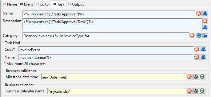
On this tab you configure the parameters of the awaited event which is handled as an
Intermediate Event Task. The Business milestone usually sets the current
DateTime for process activity analysis and reports.
Warning
The task kind feature is deprecated. These fields only appears if you activate it in Deprecation Preferences or if there are already values inscribed. Instead use the category field to categorize your tasks.
You can set the name of the business calendar that should be used for the task. In the
context of the task ivy.cal will return this business calendar
regardless of what you've set for the case.
For more information about business calendar administration see the engine guide.
For more information about business calendar usage see the Public API of
ch.ivyteam.ivy.application.calendar.IDefaultBusinessCalendar.
On this tab you can configure the output of the element (i.e. the data that leaves
the element). You can use the variable result that holds additional
information about the event received by the Java class.
See Output Tab for a more detailed description.
Note
For each incoming connection you have a separate inX object available which carries the data of the Xth input. Hover with the mouse over the incoming connections of the element to learn which input connection corresponds to which variable.
 The Call & Wait Intermediate Event element is located in the Event &
Gateway drawer of the process editor palette.
The Call & Wait Intermediate Event element is located in the Event &
Gateway drawer of the process editor palette.
This element is one of Axon.ivy facilities to integrate custom-made software, legacy systems, proprietary applications or any other external system through an Axon.ivy Java interface. The Call & Wait element is slitted into a Call part and a Wait part. The Call part is similar to the Program Interface process element. It can be used to call (send request) an external system. Whereas the Wait part is similar to the Intermediate Event element and can be used to wait for the response from the external system. For the process designer the use of a Call & Wait element is easier compared to the use of a Program Interface followed by an Intermediate Event because he only has to configure one Java class and does not have to care about event identifiers.
The Call part of the element will instantiate a
Java class that must implement the interface IUserAsynchronousProcessExtension and will call the method
performRequest each time a process comes to the Call & Wait
element. The common way to implement a Call bean is to extend the abstract base class
AbstractUserAsynchronousProcessExtension.
The Wait part of the element will interrupt the process execution and waits for an external event to occur. Technically spoken the current task will be ended and a new system task is created that waits for the event. If the event is fired the new task and therefore the process after the Call & Wait element will be executed.
You provide a listener for the external event by implementing a public static inner
Java class of the Call part with the name IntermediateEvent that implements
the IProcessIntermediateEventBean interface. The Call & Wait
element instantiates the IntermediateEvent Java class. It can then trigger
the event by calling the method fireProcessIntermediateEventEx on the
Axon.ivy runtime engine IProcessIntermediateEventBeanRuntime. The common way to implement
a Wait (Intermediate Event) bean is to extend the abstract base class AbstractProcessIntermediateEventBean.
The interface also includes an inner editor class to parametrize the beans. The editor provides one configuration which is set on both beans the Call and the Wait bean. You will find the documentation of the interface and the abstract class in the Java Doc of the Axon.ivy Public API.
This tab is included in the mask of all process elements and contains the name and a description of the element. See Name Tab for a more detailed description.
On this tab you set the Java class which implements the interface IUserAsynchronousProcessExtension and defines a public static
inner class called IntermediateEvent that implements the interface
IProcessIntermediateEventBean. This class is called when the
Call & Wait step is executed. Furthermore, you can define exception handlers to
react on errors such as not reachable systems, insufficient privileges and many
more.
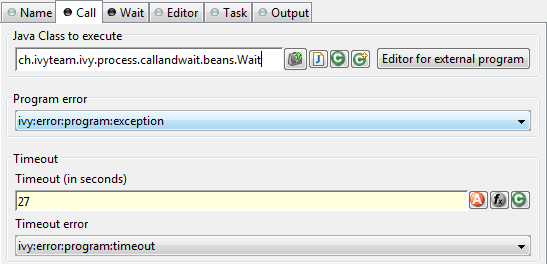
- Java Class to Execute
-
The fully qualified name of the Call & Wait Java class implementing
IUserAsynchronousProcessExtensionand a public static inner class calledIntermediateEventthat implements the interfaceIProcessIntermediateEventBean. Use the New Bean Class Wizard () to create a new Java source
file with an example implementation of the bean class. Tip
You can add a graphical configuration editor for the Java call (i.e. setting the parameter values) on the Call & Wait inscription mask. See section Tab Editor for more details.
- Program Error
-
Occurs whenever an exception is thrown during the execution of the class. The error can be handled by a catching “Error Start”.
- Timeout
-
Sets a timeout for the return of the call to the Call part Java class.
- Timeout Error
-
Occurs when the timeout is reached. The error can be handled by a catching “Error Start”.
On this tab you define the timeout behaviour during the Wait part of the element.
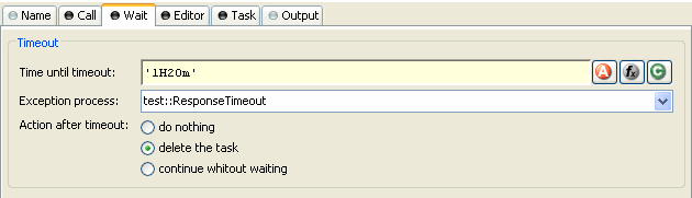
- Timeout
-
Here you can specify a time (Duration) how long the current case should wait for an intermediate event and what should happen if no event was received after this time. You can optionally start an exception process, delete the waiting task or continue the waiting task without receiving an intermediate event.
This tab displays the editor, that can be integrated in the external Java bean of the
process element. The editor is implemented as an inner public static class of the Java bean
class and must have the name Editor. Additionally the editor class must
implement the IProcessExtensionConfigurationEditorEx interface. The common way to
implement the editor class is to extend the abstract base class AbstractProcessExtensionConfigurationEditor and to override the
methods createEditorPanelContent, loadUiDataFromConfiguration and
saveUiDataToConfiguration. The method createEditorPanelContent
can be used to build the UI components of the editor. You can add any AWT/Swing component to
the given editorPanel parameter. With the given editorEnvironment
parameter, which is of the type IProcessExtensionConfigurationEditorEnvironment, you can create text
fields that support ivyScript and has smart buttons which provide access to the process
data, environment functions and Java classes.
Here is an example of such an editor:
As you can see, the editor provides you access to any process relevant data, which can be used by your own process elements. For instance, you can easily transfer process data to your legacy system.
The following part shows the implementation of the editor shown above. As mentioned above
Axon.ivy provides the IIvyScriptEditor which represents a text field with ivyScript support
and smart buttons. Inside createEditorPanelContent use the method
createIvyScriptEditor from the editorEnvironment parameter to
create an instance of such an editor. Use the loadUiDataFromConfiguration
method to read the bean configuration and set them to the UI components. Inside this method
you can use the methods getBeanConfiguration or
getBeanConfigurationProperty to read the bean configuration. Use the method
saveUiDataToConfiguration to save the data in the UI components to the bean
configuration. Inside this method you can use the methods setBeanConfiguration
or setBeanConfigurationProperty to save the bean configuration.
  public static class Editor extends AbstractProcessExtensionConfigurationEditor
  {
    private IIvyScriptEditor editorUser;
    private IIvyScriptEditor editorEventTyp;
    private IIvyScriptEditor editorLinkId;
    private IIvyScriptEditor editorFieldValue;

    @Override
    protected void createEditorPanelContent(Container editorPanel,
            IProcessExtensionConfigurationEditorEnvironment editorEnvironment)
    {
      editorPanel.setLayout(new GridLayout(4,2));
      editorUser = editorEnvironment.createIvyScriptEditor(null,null, "String");
      editorEventTyp = editorEnvironment.createIvyScriptEditor(null,null, "String");
      editorLinkId = editorEnvironment.createIvyScriptEditor(null, null, "String");
      editorFieldValue = editorEnvironment.createIvyScriptEditor(null, null);

      editorPanel.add(new JLabel("User"));
      editorPanel.add(editorUser.getComponent());
      editorPanel.add(new JLabel("Event Typ"));
      editorPanel.add(editorEventTyp.getComponent());
      editorPanel.add(new JLabel("Link-Id"));
      editorPanel.add(editorLinkId.getComponent());
      editorPanel.add(new JLabel("Feldwert"));
      editorPanel.add(editorFieldValue.getComponent());
    }

    @Override
    protected void loadUiDataFromConfiguration()
    {
      editorUser.setText(getBeanConfigurationProperty("User"));
      editorEventTyp.setText(getBeanConfigurationProperty("EventTyp"));
      editorLinkId.setText(getBeanConfigurationProperty("LinkId"));
      editorFieldValue.setText(getBeanConfigurationProperty("Feldwert"));
    }

    @Override
    protected boolean saveUiDataToConfiguration()
    {
      setBeanConfigurationProperty("User", editorUser.getText());
      setBeanConfigurationProperty("EventTyp", editorEventTyp.getText());
      setBeanConfigurationProperty("LinkId", editorLinkId.getText());
      setBeanConfigurationProperty("Feldwert", editorFieldValue.getText());
      return true;
    }
  }
At runtime you have to evaluate the IvyScript the user have entered into the ivy script
editors. If you implement for example the AbstractUserProcessExtension class there is a perform method which is
executed at runtime. At this point you want to access the configured data in the editor. The
following code snippet show how you can evaluate the value of an IIvyScriptEditor. If you use the IIvyScriptEditor you only get the value by calling the
executeIvyScript method of the AbstractUserProcessExtension.
  public CompositeObject perform(IRequestId requestId, CompositeObject in,
     IIvyScriptContext context) throws Exception
  {
    IIvyScriptContext ownContext;
    CompositeObject out;
    out = in.clone();
    ownContext = createOwnContext(context);

    String eventtyp = "";
    String linkId = "";
    String fieldValue = "";
    String user= "";

    user = (String)executeIvyScript(ownContext, getConfigurationProperty("User"));
    eventtyp = (String)executeIvyScript(ownContext, getConfigurationProperty("Event Typ"));
    linkId = (String)executeIvyScript(ownContext, getConfigurationProperty("Link-Id"));
    fieldValue = (String)executeIvyScript(ownContext, getConfigurationProperty("Feldwert"));

    // add your call here

    return out;
  }
On this tab you configure the parameters of the awaited event which is handled as an
Intermediate Event Task. The Business milestone usually sets the current
DateTime for process activity analysis and reports.
Warning
The task kind feature is deprecated. These fields only appears if you activate it in Deprecation Preferences or if there are already values inscribed. Instead use the category field to categorize your tasks.
You can set the name of the business calendar that should be used for the task. In the
context of the task ivy.cal will return this business calendar
regardless of what you've set for the case.
For more information about business calendar administration see the engine guide.
For more information about business calendar usage see the Public API of
ch.ivyteam.ivy.application.calendar.IDefaultBusinessCalendar.
On this tab you can configure the output of the element (i.e. the data that leaves the element). You can use the variable result that holds additional information about the event received by the Wait part Java class.
See Output Tab for a more detailed description.
Note
For each incoming connection you have a separate inX object available which carries the data of the Xth input. Hover with the mouse over the incoming connections of the element to learn which input connection corresponds to which variable.
 The Process End Page element is located in the Event &
Gateway drawer of the process editor palette.
The Process End Page element is located in the Event &
Gateway drawer of the process editor palette.
This tab is included in the mask of all process elements and contains the name and a description of the element. See Name Tab for a more detailed description.
On this tab you could define the web page displayed when a case ends with this End Page Element.
- Dialog Page
-
Pages can be referenced from the content management system or the web content directory. The wizard allows you to create, select or edit pages.
Please refer to Creating and Editing HTML Pages in the HTML chapter for a more thorough explanation of this tab section.
 The Error End Event element is located in the
Event & Gateway drawer of the process editor palette.
The Error End Event element is located in the
Event & Gateway drawer of the process editor palette.
The Error End Event can be used to leave the happy path of a process by throwing an error (e.g. if an approval is denied). It can also be used to re-throw previously catched errors.
See the Error Handling concept for sample use cases.
This tab is included in the mask of all process elements and contains the name and a description of the element. See Name Tab for a more detailed description.
On this tab you can configure the Error Code of the error that will be thrown or the error object that should be re-thrown.
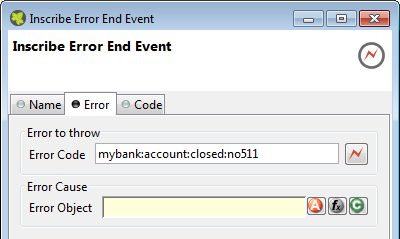
 The Process End element is located in the Event &
Gateway drawer of the process editor palette.
The Process End element is located in the Event &
Gateway drawer of the process editor palette.
This tab is included in the mask of all process elements and contains the name and a description of the element. See Name Tab for a more detailed description.
 The User Task element is located in the
Activity drawer of the process editor palette.
The User Task element is located in the
Activity drawer of the process editor palette.
The User Task element calls a User Dialog in a new Task. Thus, it combines the behavior of a Task Switch Event and a User Dialog. You can either call a normal Html Dialog or an Offline Dialog - they both are based on JSF technology and can run in a Web Browser as well as on a mobile client.
This tab is included in the mask of all process elements and contains the name and a description of the element. See Name Tab for a more detailed description.
The Call tab defines what User Dialog component should be called and how it should be started. The input parameters for the selected start method can be mapped here.
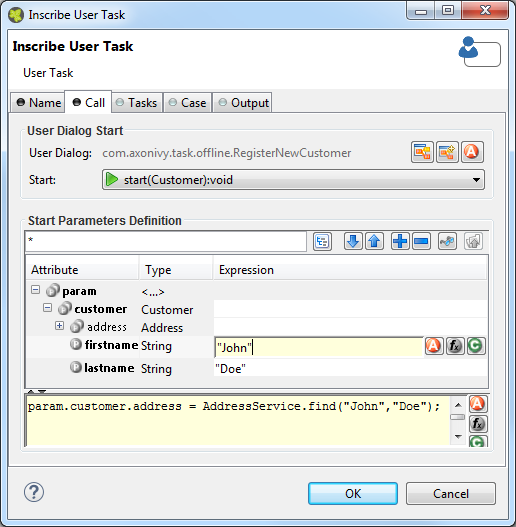
- User Dialog
-
Defines the User Dialog to be started by it's ID. The referenced User Dialog can either be a normal JSF based dialog component (Html Dialog) or a JSF based dialog that is designed for offline usage (Offline Dialog).
 Selects an existing User Dialog
  Creates a new User Dialog and uses it
  Uses a dynamically defined ID
from a data class attribute
Uses a dynamically defined ID
from a data class attribute Note
The behavior of the task will be noticeable different either if you select an Html Dialog or an Offline Dialog. By selecting an Offline Dialog, an Offline Task - designed for processing without continuous connection to the workflow server - will be generated.
- Start
-
Defines the start method that should be called on the selected User Dialog.
If the User Dialog to be started is defined dynamically, then the start cannot be selected. Instead the default start() method (no input, no output) will be called by default. If this method does not exist on the dynamically defined User Dialog, then a runtime error will occur.
If the User Dialog to be started is defined statically (i.e. with a specific ID) then the start combo box offers a list of all start methods that are declared by the selected User Dialog.
- Start Parameters Definition
-
Define the input parameters for the called User Dialog.
If the selected start method requires any parameters, those may be mapped here to an param object, which offers a field for each declared start method parameter. You can define each parameter individually from the calling process's data.
Tip
Alternatively you can define the call parameters in the scripting field below the attribute table, e.g. if you need to perform some calculation in order to define a call parameter. You can also mix the two forms, in which case the table's definitions will be executed before the scripting block.
Note
The result values of the started User Dialog (if any) are mapped back onto the calling process's data on the Output tab. They are available as fields on a result variable.
On this tab you can configure the Task of this User Task. See “Task Tab” in the Task Switch Gateway element.
On this tab you can configure the Case of this User Task. See “Case Tab” in the Task Switch Gateway element.
On this tab you can configure the output of the element (i.e. the data that leaves the element). See Output Tab for a more detailed description.
Note
Additionally to the regular variables of the Output Tab you have the following variable available:
- result
-
If the selected start method defines return parameters they will be available as fields of the result variable.
The variable is not available if the start method does not return any values (i.e. void).
 The Web Page element is located in the Activity
drawer of the process editor palette.
The Web Page element is located in the Activity
drawer of the process editor palette.
This element presents an interactive web page to the user via his browser and may be defined in the CMS or externally by a .html, or .jsp file.
For each exit of this element (the outgoing arrows from this element) a link is set that defines which way the process proceeds. By clicking on such a link (it may be a simple link or one combined with an input form) the user carries the data object with the process data to the appropriate exit, i.e. process path.
In case of a form the data that have been entered into it will be assigned to the process data attributes.
This tab is included in the mask of all process elements and contains the name and a description of the element. See Name Tab for a more detailed description.
On this tab you set the dialog page and its properties. In addition, you are able to create the Web Page from scratch and store it in the CMS.
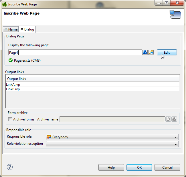
- Dialog Page
-
The selected page will be displayed in the user's browser whenever the element is activated by the process. Pages can be referenced from the content management system or the web content directory. The wizard allows you to create, select or edit pages.
Please refer to Creating and Editing HTML Pages in the HTML chapter for a more thorough explanation of this tab section.
- Output Links
-
List of the links with which the process may proceed to the next step. You can edit the names of the links as you like but they always need to have an .ivp file extension. The links appear in the order they were connected with the HTML Page element. Pausing the mouse cursor shortly over one of the outgoing arrows of the element shows a tool tip that indicates the name of the corresponding link.
- Form Archive
-
Each page (including the forms located on it and the inputs of the user) are archived on the Axon.ivy Engine. The archived pages (forms) are associated with the running case and the running task and can be inspected (viewed) afterwards in the workflow user interface.
- Responsible Role
-
Restricts the access to this dialog to the given role.
- Role Violation error
-
This error is thrown whenever a user tries to access the dialog page without having granted the required role. The error can be handled by a catching “Error Start” or by an “Error Boundary Event”
 The User Dialog element is located in the
Activity drawer of the process editor palette.
The User Dialog element is located in the
Activity drawer of the process editor palette.
The User Dialog element is used to call a User Dialog from a process. You can both start User Dialogs from a business process as well as from another User Dialog. Input and return parameters for/from the started User Dialog can be mapped using the call and output tabs of this element.
If a User Dialog is opened from within another User Dialog's logic then certain restrictions apply (see below).
This tab is included in the mask of all process elements and contains the name and a description of the element. See Name Tab for a more detailed description.
The Call tab defines what User Dialog component should be called and how it should be started. The input parameters for the selected start method can be mapped here.
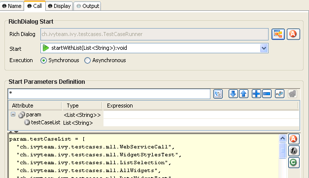
- User Dialog
-
Defines the User Dialog component to be started by it's ID.
You can either select a Rich Dialog component or a Html Dialog component by clicking on the User Dialog Browser (
) button or by defining the ID
dynamically from a data class attribute by clicking
on the Attribute () button. - Start
-
Defines the start method that should be called on the selected User Dialog.
If the User Dialog to be started is defined dynamically, then the start cannot be selected. Instead the default start() method (no input, no output) will be called by default. If this method does not exist on the dynamically defined User Dialog, then a runtime error will occur.
If the User Dialog to be started is defined statically (i.e. with a specific ID) then th start combo box offers a list of all start methods that are declared by the selected User Dialog.
- Execution (only available for Rich Dialogs)
-
Defines whether the selected Rich Dialog should be started synchronously or asynchronously.
Rich Dialogs are normally started synchronously, i.e. the calling process will stop and wait for the Rich Dialog to close before it continues. If you start a Rich Dialog asynchronously, then the calling process will immediately continue and will not wait for the started Rich Dialog to return any parameters. As a consequence of this, the called Rich Dialog will be running in parallel to the continuing process and it's return parameters will not be considered for further execution.
Note
If a synchronous Rich Dialog is started from within a Rich Dialog process then it will always open as a modal dialog. In this case, all target parameters of the Display Tab will be ignored. Any custom window configuration, however, will be used and applied for the modal dialog.
If you call a synchronous Rich Dialog from a callable process then the specification of the Display parameters makes sense, because the callable may both be invoked from a business process (in which case they are considered) or a Rich Dialog process (in which chase they are ignored).
Warning
Do not open synchronous Rich Dialogs inside a Rich Dialog start method.
This will not work for technical reasons, because the initialization of the outer Rich Dialog will not have been completed at this point of time.
You may, however, open any number of asynchronous Rich Dialogs inside a start method.
If you'd like to open a synchronous Rich Dialog immediately after some Rich Dialog becomes visible, then you should do this in a deferred event process that you trigger with the usage of a hidden button in conjunction with
ivy.rd.clickDeferred(..).See the similar warning note of the Synchronize UI process element for an example of a deferred UI process execution.
- Start Parameters Definition
-
Define the input parameters for the called User Dialog.
If the selected start method requires any parameters, those may be mapped here to an param object, which offers a field for each declared start method parameter. You can define each parameter individually from the calling process's data.
Tip
Alternatively you can define the call parameters in the scripting field below the attribute table, e.g. if you need to perform some calculation in order to define a call parameter. You can also mix the two forms, in which case the table's definitions will be executed before the scripting block.
Note
The result values of the started User Dialog (if any) are mapped back onto the calling process's data on the Output tab. They are available as fields on a result variable.
- User Context (only available for Rich Dialogs)
-
Shows the current Rich Dialog User Context configuration.
Press the button configure to edit the configuration in a separate dialog.
Note
The Rich Dialog User Context is used to store the UI State.
The Display tab defines where the Rich Dialog is opened. If you want to open the Rich Dialog in a new Window you can ignore this tab.
- Target Location
-
Define here where the started Rich Dialog should open. The target of a call is always a Display container inside a Window, therefore you need to specify both a display and a window.
Note
Depending on whether the Rich Dialog is started from a business process or a callable process or from within another Rich Dialog you have different options available for the target location selection.
The option THIS both for display and window is only available if the Rich Dialog is started directly from within another Rich Dialog, because it uses the surrounding dialog as a reference.
If - at runtime! - a synchronous Rich Dialog is opened from inside a callable process that was invoked from a Rich Dialog process, then all target location parameters will be ignored and the Rich Dialog will be shown inside a modal dialog window.
If the Rich Dialog is invoked directly (e.g. not via a callable process) from a Rich Dialog process, then the display tab shows the following message, because it can be determined for sure that the Rich Dialog will open modally:
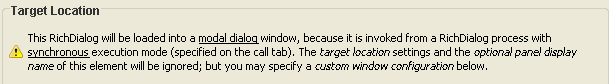
Target location settings can then not be specified for this element. This behavior only applies to synchronous Rich Dialogs that are called from a Rich Dialog process.
Possible target window specifications:
- THIS
-
The Rich Dialog will be opened in the same window as the calling Rich Dialog. (This option is not available for Rich Dialogs that are opened from a business process or a callable sub process).
- NEW
-
A new window will be opened to show the Rich Dialog. The type and layout of the new window can be specified by selecting a window type.
Note
The system offers some basic window types like card or tabbed, but window types can also be specified by the user inside the configuration editor. A window type is nothing more than a window with a specific Rich Dialog (that defines at least one display component), which will serve as basic content of the window. The Rich Dialog that you actually want to load will then be loaded onto the/a display of the Rich Dialog that specifies the window type. Example: the tabbed window type uses a Rich Dialog that only consists of a tabbed display.
- EXISTING
-
A specific window id must be provided. The Rich Dialog will then be loaded into the window that is referenced by the that window id.
- DEFAULT
-
The Rich Dialog will be shown inside the singleton default window of the application. The default window will be created and brought to front, if it isn't open yet.
- APPLET
-
The Rich Dialog will be opened inside an applet. Obviously this option only makes sense inside a HTML environment/business process. For an applet, a window type may be specified, which will be used for the applets (internal) layout.
You may also specify a custom applet configuration (see Custom Applet Configuration below) to specify the applet tag's rendering properties on the HTML page.
Warning
Please note that for technical reasons only a single instance of an applet can exist per user and session!
Warning
If you work with applets, then you must start your Axon.ivy processes that open the applets from an external browser. The internal browser of Axon.ivy is not able to show applets for security reasons.
To start your applet processes from an external browser proceed as follows:
-
Start the engine to compile and show the list of startable process starts.
-
Open an external browser and navigate to
http://localhost:8081/ivy/ -
Start your applet process with a click on the respective link.
-
Possible target display specifications:
- TOP
-
The Rich Dialog will be loaded onto the first display that is found in the component hierarchy of the specified target window.
- THIS
-
The Rich Dialog will be opened on the same display as the calling Rich Dialog, i.e. as a sibling of the surrounding dialog. (This option is not available for Rich Dialogs that are opened from a business process or a callable sub process).
- SPECIFIC
-
The id of a display must be provided. This display is then searched within the specified target window and the Rich Dialog will be loaded onto it, if it is found.
- Custom Window/Applet Configuration
-
The appearance of the window or applet to open may be configured here.
Note
Whether the here defined parameters are actually used at runtime, depends on the specific execution context. If the Rich Dialog is loaded onto an existing window (e.g. with
THISorEXISTING) then the window configuration will obviously not be used.If the Rich Dialog is opened as a modal dialog (because it is synchronous and invoked from a Rich Dialog process) then the window configuration will be used. Similarly it will be applied to
NEWwindows and toAPPLETwindows (for the latter in a slightly modified form).If the
DEFAULTwindow does not yet exist, then the window configuration will be used to create it, otherwise it will be ignored.Activate the option Specify a custom window/applet configuration.
If you've specified a window target, then the title and size of the new window to be opened may be specified (if no size is specified, then the window's size is calculated from the opened Rich Dialog's preferred size). You can also specify whether the new window should be resizeable, centered and support maximization.
Use the option close after last rich dialog if the window should be closed automatically when the last Rich Dialog that it contains is closed.
Tip
If you don't specify a custom window/applet configuration then the default configuration will be used: the new window's ID will be used as title, the window will be resizeable and centered and closed after the last rich dialog.
If you've specified an applet target, then resizeable, centered and close after last rich dialogare not available. Instead you may optionally define the URI of a page in the content management system that will be used to render the applet.
Inside that page's HTML code, you may use two predefined variables,
${PAGE_TITLE}and${APPLET}.${PAGE_TITLE}will be filled with the title that is specified inside the custom display configuration.${APPLET}will be replaced with HTML code to render the applet on the page. The specified width and height and the optional maximize flag will determine the applets size on the page.How to create a custom applet configuration
Create a content object with type source in the CMS. Enter the code of a valid HTML page as the content object's value. Use the predefined variables
${PAGE_TITLE}and${APPLET}to specify where title and applet tag should be inserted into the HTML code.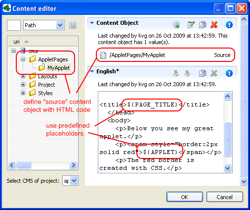
You can use the following example code:
<!DOCTYPE HTML PUBLIC "-//W3C//DTD HTML 4.01//EN" "http://www.w3.org/TR/html4/strict.dtd">
<html>
<head>
  <title>${PAGE_TITLE}</title>
</head>
<body>
  <p>Below you see my great applet.</p>
  <p><span style="border:2px solid blue">${APPLET}</span></p>
  <p>The <span style="color:blue">blue</span> border is created with CSS.</p>
</body>
</html>
After you've defined the applet page HTML code, open the Rich Dialog element from where you want to start the applet. Specify a custom applet configuration and enter the URI of the source content object that you just created in the Page Uri field.
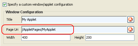
Now open an external browser (as explained above) and start the applet business process from there. Something similar to the following screen shot should be the result of your first RichApplet invocation:
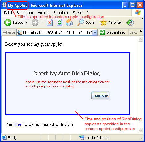
Note
If you don't specify a custom applet configuration, then the applet will be rendered on a page that is specified by the selected applets window type or - if that window type does not specify a custom applet configuration - on an empty page with a default size of 400 x 400 pixel.
Tip
Usually you open your Rich Applets sequentially, one at a time. However, if you choose to invoke another process that opens another asynchronous
APPLETRich Dialog and if there's already a RichApplet running, then the loading of the new Rich Dialog will be redirected to the already existing applet (similar to theDEFAULTapplication window). - Panel Display Name
-
Depending on the capabilities of the target display there may be the possibility to show a name for the started Rich Dialog's panel (e.g. the tab title if the target display is a Tabbed Display). This optional display name can be entered here, either as constant value or dynamically (use the
button to select from process data). If the field
is left empty, then the Rich Dialog name will be used as display
name. - Panel Display Icon
-
Depending on the capabilities of the target display there may be the possibility to show an icon for the started Rich Dialog's panel.
- Custom Panel Display Parameters
-
Depending on the capabilities of the target display there may be custom parameters to define how the started Rich Dialog's panel is displayed.
Consult the documentation of the display to find out what custom parameters are available.
On this tab you can configure the output of the element (i.e. the data that leaves the element). See Output Tab for a more detailed description.
Note
Additionally to the regular variables of the Output Tab you have the following variables available:
- result
-
If the selected start method defines return parameters they will be available as fields of the result variable.
The variable is not available if the start method does not return any values (i.e. void).
- panel
-
The panel of the just finished User Dialog is still available at the time when the output is calculated. You can e.g. use this variable to request some inner state of the just finished User Dialog (apart from the returned values available on the result variable).
 The Script Step element is
located in the Activity drawer of the process editor palette.
The Script Step element is
located in the Activity drawer of the process editor palette.
With this element you can perform any transformation of the process data or start some other processing in order to make preparations for later steps.
Warning
It is strongly recommended to use the dedicated process elements if you intend to use specific functionality and/or technology (such as invoking Web Services, querying Databases and so on) as these elements encapsulate their use and handle exceptions internally.
This tab is included in the mask of all process elements and contains the name and a description of the element. See Name Tab for a more detailed description.
On this tab you can configure the output of the element (i.e. the data that leaves the element). See Output Tab for a more detailed description.
On this tab you can execute any script, e.g. define output data of this element. See Code Tab for a more detailed description.
Tip
The entered code will be executed after the execution of the output tab. Although this may seem a bit counter-intuitive at first, you should simply regard the code tab as an alternative way of defining output data. The general recommendation is to use the output table to define simple assignments and the code tab if more extensive scripting is needed to calculate data.
- Disable Permission Checks (Execute this Script Step as SYSTEM)
-
With this option enabled the scripts from the Output and Code Tab runs without security permission checks. The execution of the scripts will never throw any PermissionDeniedException.
Warning
Use this possiblity with caution! In this case you as process developer are reponsible that only authorized users can reach this Script Step in the process.
 The Database Step (DB Step) element is located in
the Activity drawer of the process editor palette.
The Database Step (DB Step) element is located in
the Activity drawer of the process editor palette.
With this element you can execute SQL commands on the database server. You can access all the databases that are defined in the DB Configuration.
This tab is included in the mask of all process elements and contains the name and a description of the element. See Name Tab for a more detailed description.
Here you define which SQL command you want to execute on which database. Depending on the kind of SQL command you are supported during the construction of your command.
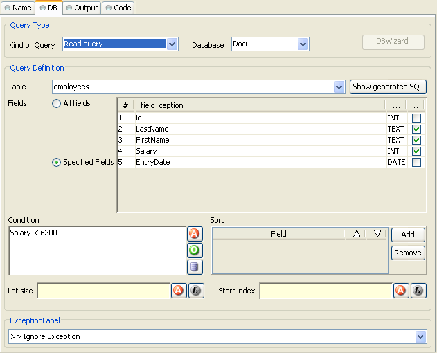
- Kind of Query
-
Choose the kind of query you like to perform. Axon.ivy offers dedicated UI support for the most common query types such as Select (Read Query), Insert (Write Query), Update (Update Query) and Delete (Delete Query).
If you require some non-standard SQL or if you want to issue a complex SQL statement that is not covered by the Query Definition mask then you may also select Any Query and write pure SQL instead. Expanding of process attributes will also work in the Any Query mode.
Warning
The use of the Any Query option can lead to SQL injection vulnerabilities if not used carefully.
E.g. if a
Stringvariable is passed into a query then an attacker could provide a valid partial SQL statement which is then executed in the context of the query.Assume the following SQL statement is configured as an SQL query:
SELECT * FROM
									Subscriber WHERE Name LIKE 'in.searchText%'
. Now if an attacker manages to pass a valid SQL statement into thein.searchTextvariable then a so called SQL injection takes place, which can result in a complete data breach on the configured database. Process designers are responsible to only pass sanitized data into an SQL query. In some cases it might be better to access the Database with JPA/Hibernate or prepared statements using JDBC. For more information see: SQL Injection Prevention Cheat Sheet - Database
-
Choose the database on which the command is executed. The database must be configured in the DB configuration. Depending on the active environment the right connection properties of the database will be used.
Warning
Please note that the DB2 database is currently not fully supported by the DB Step. The only query kind that is suitable for DB2 connections is Any Query. For all other query kinds the Query Definition mask is currently not working correctly (e.g. query fields can not be edited / defined).
There is also an
IvySystemDatabasedatasource which points to the current System Database. Normally you would prefer your own database to split valuable customer data from the system data.Warning
Do not manipulate system database tables prefixed with
IWA_within theIvySystemDatabasethis could lead to unexpected runtime behavior. - Query Definition
-
Depending on the type of query you can compose your command with almost no knowledge about databases and SQL.
- Table
-
The name of the database table to read from, insert into, update in or delete from.
- Fields
-
The fields of the database table to read from, insert values into or update values in.
- Condition
-
A condition that filters the rows of the table to read, update or delete.
- Sort
-
Defines the fields after which the rows that are read from the database are sorted.
- Lot size
-
Defines how many rows are read from the database. Enter 0 or leave it empty for no limitation.
- Start index
-
Defines the number of the row that is the first row in the read recordset out of the overall rows which match the condition.
- Quote IvyScript variables
-
IvyScript variables in the SQL query are quoted depending on the data type of the value of the variable. For example string values are quoted with single quotes (e.g. hello -> 'hello'). Sometime you do not want that the values are quoted because the variable do not contain a single value but a part of an SQL query (e.g. "id=123 AND name=ivy"). Therefore you can disable the quoting with this check box.
- Error
-
Is thrown whenever errors during the execution of the database command occur. The error can be handled by a catching “Error Start” or by an “Error Boundary Event”.
Tip
SQL experts can review the generated SQL command by clicking on the Show generated SQL or by choosing Any other query in the query combo box.
On this tab you can configure the settings for data cache access or invalidation. See Data Cache Tab for a more detailed description.
On this tab you can configure the output of the element (i.e. the data that leaves the element). See Output Tab for a more detailed description.
On this tab you can execute any script, e.g. define output data of this element. See Code Tab for a more detailed description.
Tip
The entered code will be executed after the execution of the output tab. Although this may seem a bit counter-intuitive at first, you should simply regard the code tab as an alternative way of defining output data. The general recommendation is to use the output table to define simple assignments and the code tab if more extensive scripting is needed to calculate data.
 The Web Service Call Step element is located in the
Activity drawer of the process editor palette.
The Web Service Call Step element is located in the
Activity drawer of the process editor palette.
Using the Web Service Call step you can invoke Web Services. Within the element you first have to select a Web Service configuration (predefined in Web service configuration editor). According to the selected configuration you then may select the port type and the Web Service operation you want to invoke. Necessary arguments must be specified for the chosen Web Service operation. You might want to map return values to process data (see Output tab), and you can even use own IvyScript code as well (see Code tab).
This tab is included in the mask of all process elements and contains the name and a description of the element. See Name Tab for a more detailed description.
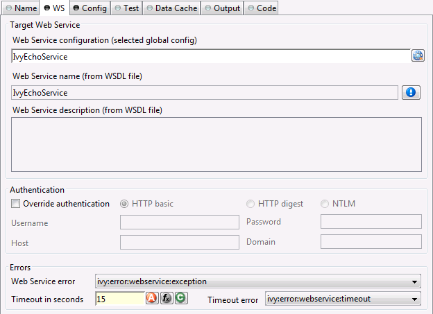
The tab WS is included in the mask of Web Service Call Step element. It features the following entries:
- Web Service Configuration
-
The selected global Web Service configuration. Web Service configuration of required projects can be used by this element too. Authentication information defined by such referred Web Service configuration can be overridden.
Tip
Starting typing the name of the global configuration and the configuration selection window will appear. Hitting the DEL key will erase selection.
- Web Service Name
-
This is an information field. It shows the Web Service name extracted from the corresponding WSDL file of the selected Web Service configuration.
Tip
By clicking on the info icon, a new window appears and shows additional information about the generated Web Service classes.
- Web Service Description
-
This is also an information field. If the WSDL file of a Web Service configuration contains a description, then it is extracted at Web Service class generation and displayed here.
- Override authentication
-
Normally the authentication information from the selected global web service configuration is used. If you check "override" then you must specify authentication information as well (authentication type, user name, password)
Following authentication types are available:
-
HTTP basic: HTTP basic authentication is used.
-
HTTP digest: HTTP digest authentication is used.
-
NTLM: Microsoft's NTLM authentication is used.
-
- User Name
-
This option is only available if you selected Override authentication. Name of a user is expected for authentication.
- Password
-
This option is only available if you selected Override authentication. Password for the above specified user is expected for authentication.
- Host
-
This option is only available if you selected Override authentication and NTLM authentication.
- Domain
-
This option is only available if you selected Override authentication and NTLM authentication. Specify the Windows domain of the user that should be used to authentication the user.
- Web Service error
-
Is thrown whenever an error occurs during the execution of this element. The error can be handled by a catching “Error Start” or an “Error Boundary Event”.
- Timeout in Seconds
-
You may define a timeout. When you do it, the Web Service invocation must end within a defined time period. If no response returns in time, a timeout exception is thrown.
- Timeout error
-
Is thrown if the defined timeout is reached. The error can be handled by a catching “Error Start” or an “Error Boundary Event”.
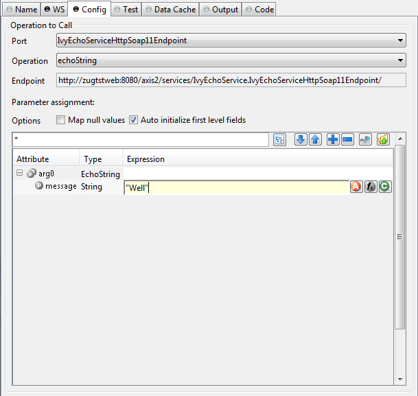
The tab Config is included in the mask of Web Service Call Step process element. It features the following entries:
- Port
-
WSDL port type to be used at Web Service invocation. Service port type may group operations according to some logical or technical aspects. See further details at Web Service configuration.
- Operation
-
Select the Web Service operation you want to invoke from server.
- Endpoint
-
Setting displayed in this field comes from the selected Web Service configuration (default end point)
- Parameter Assignment
-
According to the selected Web Service operation a parameter assignment is carried out here. Should the selected operation have no input arguments, this table will stay empty. As soon as the selected operation needs input arguments you should assign parameter values. Otherwise, it is likely that you get some errors due to unsatisfied input arguments.
Warning
If WSDL defines a parameter as a sequence of objects, the respective parameter on the generated Java client class will have an array type (on the config tab the parameter appears with type
Array<?>). IvyScript treats such Array types as if they were Lists and allows to add members (e.g.wsParamStringArray.add("a string")). In fact, Array type manipulations done with a List method (e.g.add(),remove()) will have no effect on the original Array parameter value.Members can be added to an Array parameter when they are previously stored in a temporary List. This List can then be assigned to the array parameter.
Example: Assuming our Web service "FruitOrder" expects a sequence of fruit names as strings.
List<String> listOfFruits = ["Apple", "Pear", "Strawberry"];wsParamStringArray = listOfFruits; - Map null values
-
Depending on this setting
nullvalues evaluated on the right hand side are mapped to the Web Service parameters on the left hand side. If this option is not selectednullvalues on the right hand side will be ignored. - Auto initialize first level fields
-
Depening on this setting complex fields of the Web Service parameters are auto initialized (first level only). A complex field is a field with a type that contains fields again. If this option is not selected the fields will be
nullif no values are explicitly mapped to them or one of its children.
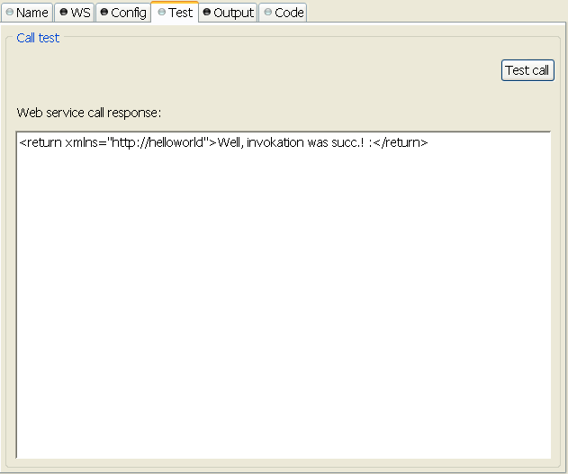
The tab Web Service Test is included in the mask of a Web Service call element. It features the following entries:
- Test call
-
You can test a configured Web Service invocation. Clicking Test Call button invokes the web service and displays the response.
Note
Since process attributes are not available at this test time, a separate window appears (only when the Web Service needs input data) to let you enter the parameter values for the test call.
- Web Service Call Response
-
The response of the Web Service invocation is displayed here. If an exception occurs, the error message is displayed.
On this tab you can configure the settings for data cache access or invalidation. See Data Cache Tab for a more detailed description.
On this tab you can configure the output of the element (i.e. the data that leaves the element). See Output Tab for a more detailed description.
On this tab you can execute any script, e.g. define output data of this element. See Code Tab for a more detailed description.
Tip
The entered code will be executed after the execution of the output tab. This may feel a bit counter-intuitive at first, but you should simply consider the code tab an alternative way of defining output data. The general recommendation is to use the output table to define simple assignments and the code tab if more extensive scripting is needed to calculate data.
 The REST Client Call Activity element is located
in the Activity drawer of the process editor palette.
The REST Client Call Activity element is located
in the Activity drawer of the process editor palette.
This tab is included in the mask of all process elements and contains the name and a description of the element. See Name Tab for a more detailed description.
On this tab you can configure the call to the REST service.
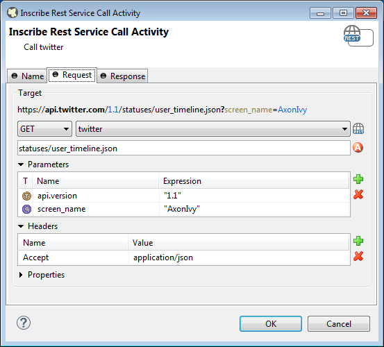
- Target
-
-
HTTP-Method: The first combo lets you select the HTTP method to use. You can choose one of the well known methods like GET, POST, PUT or DELETE.
-
REST-Client: The second combo lets you pick a pre-configured “REST Clients Configuration”.
-
Path: The text input can be used to define a resource-path. The provided path will be added to the base URI which is defined in the “REST Clients Configuration”. Use the attribute browser on the right side to insert dynamic parts to the URI.
-
Parameters: Use this table to define query parameters that should be added to the URI. Or switch the type to 'template' in order to resolve a dynamic path template with a concrete value.
The parameter value is scriptable and can therefore contain process variables or other dynamic content.
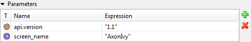
-
Headers: Will be sent with the request and can be interpreted by the target service. For instance, many REST APIs can provide data in multiple serialization formats. By setting the
Acceptheader, the preferred format can be propagated to the target service.Any other HTTP-Header can also be configured. However, the
Authorizationheader is easier to configure with an authorization feature on the “REST Clients Configuration”.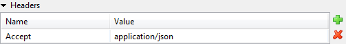
-
Properties: Are used to configure optional features or native properties of the REST client. They are globally configurable in the “REST Clients Configuration” properties. Here you can overwrite a property with dynamic values.
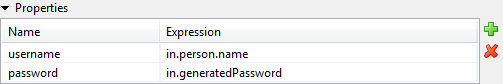
-
- Body
-
For POST and PUT requests the body section can be used to specify that data that will be sent to the REST service.
-
Raw: Define the Content-Type first and define any textual content in the editor part. The content can contain dynamic parts like process data fields. Use the action buttons left to the editor in order to insert a dynamic variable or function call.
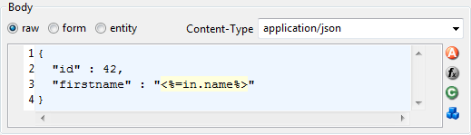
-
Form: Send form values as content of type
application/x-www-form-urlencodedThe form values are scriptable.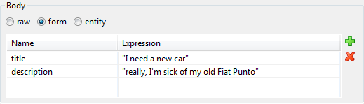
-
Entity: Send a complex object as serialized text to the remote REST service. Most Java objects should be serializable as JSON (application/json) without additional configuration.
The serialization behaviour can be configured for special needs via properties on the client. See ???
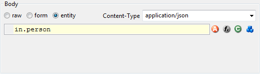
-
On this tab you can consume response from the REST service.
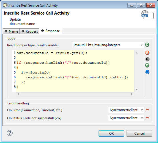
- Body
-
-
Result-Type: The first combo defines how the response entity will be read. Pick a Java type that can be mapped to response entity. The entity object is available in the 'result' variable.
See the chapter below (“JSON to Java”) for a quick comparison of response body mapping solutions.
The deserialization from JSON to a Java object can be customized with properties on the client. See ???
-
Code: Use the code editor to handle the response or its entity. In most cases, you only need to assign the 'result' variable to your process data. However, in this editor the JAX-RS 'response' variable is also available which lets you access the HTTP-status-code and other details of the HTTP response.
-
- Error handling
-
-
On Error: Choose the Error Code to throw if the REST client fails with an exception. This is typically the case if a connection or timeout problem exists. Pick '>> Ignore Error' to continue the process execution even though the REST service call failed with an exception.
-
On Status Code not successful: Fail automatically with an Error Code if the HTTP response status code is not in the 200 family. Pick '>> Ignore Error' if other status codes are valid and expected.
-
The mapping of a JSON response body to a Java object is a simple task. Think of a service that returns a complex JSON. E.g:
{
  "id": 1,
  "name": "Leanne Graham",
  "username": "Bret",
  "email": "Sincere@april.biz",
  "address": {
    "street": "Kulas Light",
    "suite": "Apt. 556",
    "city": "Gwenborough",
    "zipcode": "92998-3874",
    "geo": {
      "lat": "-37.3159",
      "lng": "81.1496"
    }
  },
  "phone": "1-770-736-8031 x56442",
  "website": "hildegard.org",
  "company": {
    "name": "Romaguera-Crona",
    "catchPhrase": "Multi-layered client-server neural-net",
    "bs": "harness real-time e-markets"
  }
}
You can handle this complex JSON object with one of these solutions:
-
Map to JSON Node: Read the result body as
JsonNodeobject. Navigate through the object tree and read its field values manually.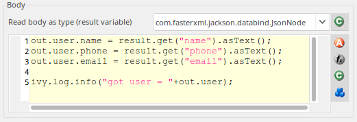
-
Map to Data Class: Create a Data Class with the attributes you need in the business process. Read the result body with this Data Class. Every attribute that matches by name (case sensitive) with an attribute in the JSON object will be mapped. Assign the
resultobject to an attribute of your process data.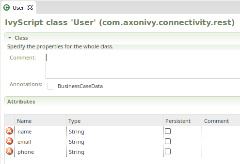
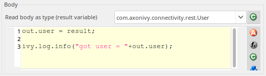
-
Map to Generated Class: Paste the JSON you receive from the service into a Java object source generator like http://www.jsonschema2pojo.org/. Generate the Java sources for the JSON structure. Download the sources and add them to a special source folder (E.g.
src_generated). Now you can read the response body to an object of this generated class.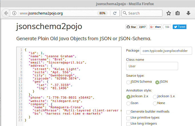
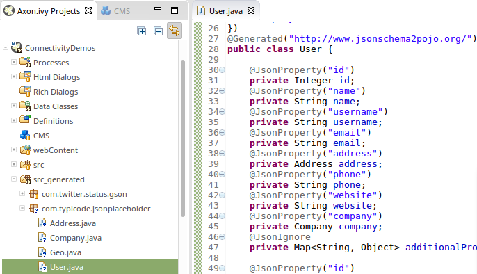
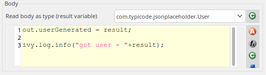
The inscription mask provides a handy UI that makes most calls to a REST service very simple. However, there are always corner cases where you need to configure something, which is not configurable on the UI. In these rare cases, you can use the fluent JAX-RS API to call the service and interpret the response. To do so you can choose 'JAX_RS' as HTTP Method. In the scripting field that became visible you can configure every detail of the REST request done by this element.
In the scripting field, the variable client holds the REST client chosen in the
Target section. The whole setup from the Target section will be
applied to this client variable.
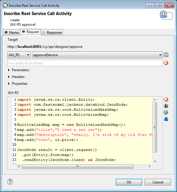
Rest Client calls can also be executed via Public API without using the Rest Client Activity.
The entry point to access Rest Clients is Ivy.rest(). The returned object is
an instance of a javax.ws.rs.client.WebTarget which is pre-configured as defined in the
“REST Clients Configuration”. It
provides fluent API to call the remote REST service.
Sample
// retrieve pre-configured rest service client
WebTarget client = Ivy.rest().client("myServiceName"):

// GET request to receive a simple string
String token = Ivy.rest().client(UUID.fromString("e00c9735-7733-4da8-85c8-6413c6fb2cd3")).request().get(String.class);

// POST request to send a complex object
Ivy.rest().client("crmService").request().post(javax.ws.rs.client.Entity.json(myPerson));
If you notice that you configure precisely the same thing on multiple Rest Client Activities you can reduce this duplication.
Instead of applying the configuration multiple times, it can be set globally on the “REST Clients Configuration”. Almost
any aspect of a Rest Client call can be configured by implementing a custom feature
(javax.ws.rs.core.Feature). Our authorization feature can be taken
as an example:
ch.ivyteam.ivy.rest.client.authentication.HttpBasicAuthenticationFeature.
 The E-Mail Step element is
located in the Activity drawer of the process editor palette.
The E-Mail Step element is
located in the Activity drawer of the process editor palette.
This element allows to send e-mails out of processes (e.g. for information or alert purposes). The general configuration must be set in the E-Mail preferences for the Axon.ivy Designer and in the Engine Administration for the Axon.ivy Engine.
With the default E-Mail preferences mails will be sent to a development SMTP server that quickly shows you the mailboxes in the 'Mail Messages' view of the Designer.
Note
In the designer the sender (from) and the recipient (to) are always taken from the E-Mail Preferences, so you can easily test whether the mails are sent correctly by using your own e-mail address (or a dedicated test address)
This tab is included in the mask of all process elements and contains the name and a description of the element. See Name Tab for a more detailed description.
In this tab the e-mail header is defined. You can use the CMS and the process data (the In variable) to compose the header fields.
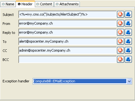
- Subject
-
The title of the e-mail to send.
- From
-
The sender of the e-mail (always use a valid e-mail address).
- Reply to
-
The e-mail address which is used by most e-mail clients when the reader clicks on "Reply" or "Reply all". Always use a valid e-mail address.
- To
-
The recipient(s) of the e-mail. Multiple recipients can be separated by a comma or semi-colon.
- CC
-
The recipient(s) in carbon copy of the e-mail. Multiple recipients can be separated by a comma or semi-colon.
- BCC
-
The recipient(s) in blind carbon copy of the e-mail. Multiple recipients can be separated by a comma or semi-colon.
- Error
-
Is thrown whenever an error occurs during the execution of this element. The error can be handled by a catching “Error Start” or by an “Error Boundary Event”.
In this tab the e-mail content is defined.
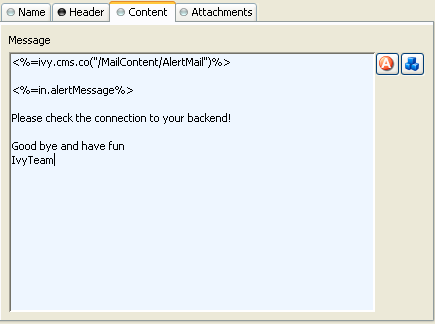
- Message
-
The text of the e-mail. Use the CMS to have messages in multiple languages.
Tip
Start your message with an
<HTML>tag to let you define your whole message in HTML format. (of course at the end of message an</HTML>is expected)
In this tab you can attach files to your e-mail. Each attachment line below on the screenshot represents one file. You can choose a file directly, take a process attribute with the type File, select a CMS entry or even build up the filename using script(s). The provided reference will be searched as CMS entry first, if no CMS entries found then the system will search the name as file in your Axon.ivy file area.
Note
CMS entry names do not have an extension (meanwhile filenames used to have one) so that the lookup order should cause no file overlapping.
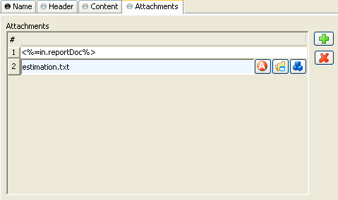
Tip
Right click on a file input line to access further commands.
 The Subprocess element is located in the
Activity drawer of the process editor palette.
The Subprocess element is located in the
Activity drawer of the process editor palette.
An embedded subprocess folds a part of a process into a box. This makes hierarchical structuring of the process model possible. Sub processes are obtained top down or bottom up. Either by selecting and wrap parts of a process or by inserting an (initially empty) embedded sub element from the palette.
This tab is included in the mask of all process elements and contains the name and a description of the element. See Name Tab for a more detailed description.
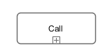 The Call Sub element is located in the Activity
drawer of the process editor palette.
The Call Sub element is located in the Activity
drawer of the process editor palette.
The Call Sub element allows to embed a process (independent subprocess) into an other. This is like jumping from the main process into the called sub process, execute the sub process and afterwards jump back. Process data attributes from the main process are mapped to parameters for the called sub process and the called sub process will return result parameters back to the main process.
Note
The input and result parameters of the called process are defined on the start element of the called process.
This tab is included in the mask of all process elements and contains the name and a description of the element. See Name Tab for a more detailed description.
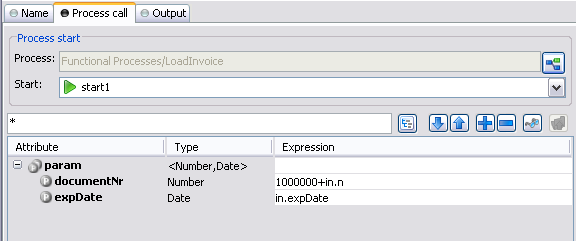
In this tab you choose the process to be called and map process data attributes to the input parameters of the called process. You can use any IvyScript expression in the parameter mapping.
On this tab you can configure the output of the element (i.e. the data that leaves the element). See Output Tab for a more detailed description.
The variable result contains the output parameters that are returned
by the called sub process (according to it's interface definition).
E.g. if the called process returns a String errorMessage and an
Employee object employee then the variable
result will have two fields: errorMessage and
employee, respectively. You can map those fields to the attributes
of the outgoing process data:
				out.msg = result.errorMessage is initialized
					? ("An error occurred during selection: "
						+ result.errorMessage)
					: "";
				out.selectedEmployee = result.employee;
 The Trigger Step element is
located in the Activity drawer of the process editor palette.
The Trigger Step element is
located in the Activity drawer of the process editor palette.
With the Trigger element its possible to start a new workflow. The trigger element triggers a Request Start element, which has an enabled triggered start mechanism. On call, the trigger element creates a case and a task with the defined configuration on the Request Start element. The new created task is returned to the Trigger element.
On call, after the creation of the new case and task, the workflow goes ahead through the process. When the created task starts (some time later, by user interaction or automatically by the system), the process starts at the Triggered Start element.
This tab is included in the mask of all process elements and contains the name and a description of the element. See Name Tab for a more detailed description.
On this tab you can configure the Start Signature and the mapping of input parameter to the process data. The Start Signature is defined by its name and its parameter type and order.
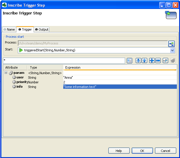
On this tab you can configure the output of the element (i.e. the data that leaves the element). See Output Tab for a more detailed description.
The variable result contains the created task that are returned by
the triggered Request
Start.
 The Program Interface Step
element is located in the Activity drawer of the process editor
palette.
The Program Interface Step
element is located in the Activity drawer of the process editor
palette.
This element is one of Axon.ivy facilities to integrate custom-made software, legacy
systems, proprietary applications or any other external system through a Java interface.
The Program Interface element will instantiate a Java class that must implement the
interface IUserProcessExtension and will call the method
perform each time a process comes to the Program Interface. The common way
to implement a Program Interface bean is to extend the abstract base class AbstractUserProcessExtension. The interface also includes an
inner editor class to parametrize the bean. You will find the documentation of the
interface and the abstract class in the Java Doc of the Axon.ivy Public API.
Note
Since 3.x this element has become somewhat obsolete, since it has become very easy to create and call your own Java classes from IvyScript. However, the PI element still provides a standardized interface to a third party Java class and can provide a custom made editor for parametrization.
This tab is included in the mask of all process elements and contains the name and a description of the element. See Name Tab for a more detailed description.
On this tab you set the Java class which implements the interface IUserProcessExtension which is called when the PI step is
executed. Furthermore, you can define exception handlers to react on errors such as
not reachable systems, insufficient privileges and many more.
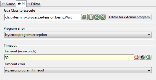
- Java Class to Execute
-
The fully qualified name of the PI Java class implementing
IUserProcessExtension. You can use default copy & paste commands, open a Java Type Browser to search for the class or you use the predefinedWaitclass which just waits for a given period of time. Use the New Bean Class Wizard () to create a new Java source
file with an example implementation of the bean class. Tip
You can add a graphical configuration editor for the Java call (i.e. setting the parameter values) on the PI inscription mask. See section Tab Editor for more details.
- Program error
-
Occurs whenever an exception is thrown during the execution of the class. The error can be handled by a catching “Error Start”.
- Timeout
-
Sets a timeout for the return call to the Java PI class.
- Timeout error
-
Occurs when the timeout is reached. The error can be handled by a catching “Error Start”.
This tab displays the editor, that can be integrated in the external Java bean of the
process element. The editor is implemented as an inner public static class of the Java bean
class and must have the name Editor. Additionally the editor class must
implement the IProcessExtensionConfigurationEditorEx interface. The common way to
implement the editor class is to extend the abstract base class AbstractProcessExtensionConfigurationEditor and to override the
methods createEditorPanelContent, loadUiDataFromConfiguration and
saveUiDataToConfiguration. The method createEditorPanelContent
can be used to build the UI components of the editor. You can add any AWT/Swing component to
the given editorPanel parameter. With the given editorEnvironment
parameter, which is of the type IProcessExtensionConfigurationEditorEnvironment, you can create text
fields that support ivyScript and has smart buttons which provide access to the process
data, environment functions and Java classes.
Here is an example of such an editor:
As you can see, the editor provides you access to any process relevant data, which can be used by your own process elements. For instance, you can easily transfer process data to your legacy system.
The following part shows the implementation of the editor shown above. As mentioned above
Axon.ivy provides the IIvyScriptEditor which represents a text field with ivyScript support
and smart buttons. Inside createEditorPanelContent use the method
createIvyScriptEditor from the editorEnvironment parameter to
create an instance of such an editor. Use the loadUiDataFromConfiguration
method to read the bean configuration and set them to the UI components. Inside this method
you can use the methods getBeanConfiguration or
getBeanConfigurationProperty to read the bean configuration. Use the method
saveUiDataToConfiguration to save the data in the UI components to the bean
configuration. Inside this method you can use the methods setBeanConfiguration
or setBeanConfigurationProperty to save the bean configuration.
  public static class Editor extends AbstractProcessExtensionConfigurationEditor
  {
    private IIvyScriptEditor editorUser;
    private IIvyScriptEditor editorEventTyp;
    private IIvyScriptEditor editorLinkId;
    private IIvyScriptEditor editorFieldValue;

    @Override
    protected void createEditorPanelContent(Container editorPanel,
            IProcessExtensionConfigurationEditorEnvironment editorEnvironment)
    {
      editorPanel.setLayout(new GridLayout(4,2));
      editorUser = editorEnvironment.createIvyScriptEditor(null,null, "String");
      editorEventTyp = editorEnvironment.createIvyScriptEditor(null,null, "String");
      editorLinkId = editorEnvironment.createIvyScriptEditor(null, null, "String");
      editorFieldValue = editorEnvironment.createIvyScriptEditor(null, null);

      editorPanel.add(new JLabel("User"));
      editorPanel.add(editorUser.getComponent());
      editorPanel.add(new JLabel("Event Typ"));
      editorPanel.add(editorEventTyp.getComponent());
      editorPanel.add(new JLabel("Link-Id"));
      editorPanel.add(editorLinkId.getComponent());
      editorPanel.add(new JLabel("Feldwert"));
      editorPanel.add(editorFieldValue.getComponent());
    }

    @Override
    protected void loadUiDataFromConfiguration()
    {
      editorUser.setText(getBeanConfigurationProperty("User"));
      editorEventTyp.setText(getBeanConfigurationProperty("EventTyp"));
      editorLinkId.setText(getBeanConfigurationProperty("LinkId"));
      editorFieldValue.setText(getBeanConfigurationProperty("Feldwert"));
    }

    @Override
    protected boolean saveUiDataToConfiguration()
    {
      setBeanConfigurationProperty("User", editorUser.getText());
      setBeanConfigurationProperty("EventTyp", editorEventTyp.getText());
      setBeanConfigurationProperty("LinkId", editorLinkId.getText());
      setBeanConfigurationProperty("Feldwert", editorFieldValue.getText());
      return true;
    }
  }
At runtime you have to evaluate the IvyScript the user have entered into the ivy script
editors. If you implement for example the AbstractUserProcessExtension class there is a perform method which is
executed at runtime. At this point you want to access the configured data in the editor. The
following code snippet show how you can evaluate the value of an IIvyScriptEditor. If you use the IIvyScriptEditor you only get the value by calling the
executeIvyScript method of the AbstractUserProcessExtension.
  public CompositeObject perform(IRequestId requestId, CompositeObject in,
     IIvyScriptContext context) throws Exception
  {
    IIvyScriptContext ownContext;
    CompositeObject out;
    out = in.clone();
    ownContext = createOwnContext(context);

    String eventtyp = "";
    String linkId = "";
    String fieldValue = "";
    String user= "";

    user = (String)executeIvyScript(ownContext, getConfigurationProperty("User"));
    eventtyp = (String)executeIvyScript(ownContext, getConfigurationProperty("Event Typ"));
    linkId = (String)executeIvyScript(ownContext, getConfigurationProperty("Link-Id"));
    fieldValue = (String)executeIvyScript(ownContext, getConfigurationProperty("Feldwert"));

    // add your call here

    return out;
  }
public class MyOwnPiBean extends AbstractUserProcessExtension {

				/**
				* @see ch.ivyteam.ivy.process.extension.IUserProcessExtension#perform(ch.ivyteam.ivy.process.engine.IRequestId,
				*      ch.ivyteam.ivy.scripting.objects.CompositeObject,
				*      ch.ivyteam.ivy.scripting.language.IIvyScriptContext)
				*/
				public CompositeObject perform(IRequestId requestId, CompositeObject in,
				IIvyScriptContext context) throws Exception {

    				IIvyScriptContext ownContext;
    				CompositeObject out;
    				out = in.clone();
    				ownContext = createOwnContext(context);

    				String eventtyp = "";
    				String linkId = "";
    				String fieldValue = "";
    				String user= "";

    				StringTokenizer st = new StringTokenizer(getConfiguration(),"|");
    				if(st.hasMoreElements())
        				user= (String)executeIvyScript(context, st.nextElement().toString());
    				if(st.hasMoreElements())
        				eventtyp = (String)executeIvyScript(context, st.nextElement().toString());
    				if(st.hasMoreElements())
        				linkId = (String)executeIvyScript(context, st.nextElement().toString());
    				if(st.hasMoreElements())
        				fieldValue = (String)executeIvyScript(context, st.nextElement().toString());

    				//do something with the values
    				return out;
  				}

    				public static class Editor extends JPanel implements IProcessExtensionConfigurationEditorEx {
        				private IProcessExtensionConfigurationEditorEnvironment env;
        				private IIvyScriptEditor editorUser;
        				private IIvyScriptEditor editorEventTyp;
        				private IIvyScriptEditor editorLinkId;
        				private IIvyScriptEditor editorFieldValue;


        				/**
        				* Constructor for the Editor object
        				*/
        				public Editor() {
            				super(new GridLayout(4,2));
        				}

        				/**
        				* Sets the configuration
        				*
        				* @param config  the configuration as an String	*/
    				public void setConfiguration(String config) {
        				StringTokenizer st = new StringTokenizer(config,"|");
        				if(st.hasMoreElements())
            				editorUser.setText(st.nextElement().toString());
        				if(st.hasMoreElements())
            				editorEventTyp.setText(st.nextElement().toString());
        				if(st.hasMoreElements())
            				editorLinkId.setText(st.nextElement().toString());
        				if(st.hasMoreElements())
            				editorFieldValue.setText(st.nextElement().toString());
    				}

    				/**
    				* Gets the component attribute of the Editor object
    				*
    				* @return this
    				*/
    				public Component getComponent() {
        				return this;
    				}

    				/**
    				* Gets the configuration
    				*
    				* @return The configuration as an String
    				*/
    				public String getConfiguration() {
        				return editorUser.getText() + "|" +  editorEventTyp.getText() +  "|" +
        					editorLinkId.getText() + "|" + editorFieldValue.getText() + "|";
    				}

    				/**
    				* @return boolean
    				*/
    				public boolean acceptInput() {
        				return true;
    				}

    				public void setEnvironment(IProcessExtensionConfigurationEditorEnvironment env) {
        				this.env = env;
        				editorUser = env.createIvyScriptEditor(null,null, "String");
        				editorEventTyp = env.createIvyScriptEditor(null,null, "String");
        				editorLinkId = env.createIvyScriptEditor(null, null, "String");
        				editorFieldValue = env.createIvyScriptEditor(null, null);

        				add(new JLabel("User"));
        				add(editorUser.getComponent());
        				add(new JLabel("Event Typ"));
        				add(editorEventTyp.getComponent());
        				add(new JLabel("Link-Id"));
        				add(editorLinkId.getComponent());
        				add(new JLabel("Feldwert"));
        				add(editorFieldValue.getComponent());

   				}
  				}
				}
 The Note element is located in the Activity
drawer of the process editor palette.
The Note element is located in the Activity
drawer of the process editor palette.
An Annotation enables comments to be inserted anywhere within a model for documentation purposes
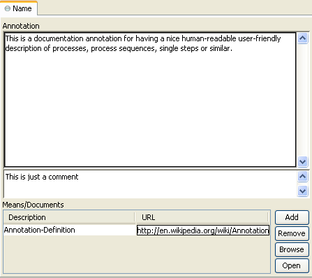
- Annotation
-
The text of the annotation. This is displayed on the process diagram fro your documentation.
- Comment
-
In this text field the function of the element is described. This text appears as Tool Tip whenever the mouse stays over the element.
- Means/Documents
-
This table lists the means being used and which documents are available at with location (given as an URL).
Tip
In generated HTML reports, a link is inserted for these document references.
 The WS Start element is located in the
WS Process drawer of the process editor palette and only available
in web service processes.
The WS Start element is located in the
WS Process drawer of the process editor palette and only available
in web service processes.
Each Web Service Start element will create a web service operation in the web service where it is located. It has input and output parameters.
This tab is included in the mask of all process elements and contains the name and a description of the element. See Name Tab for a more detailed description.
This tab is used to define the signature of the web service operation.
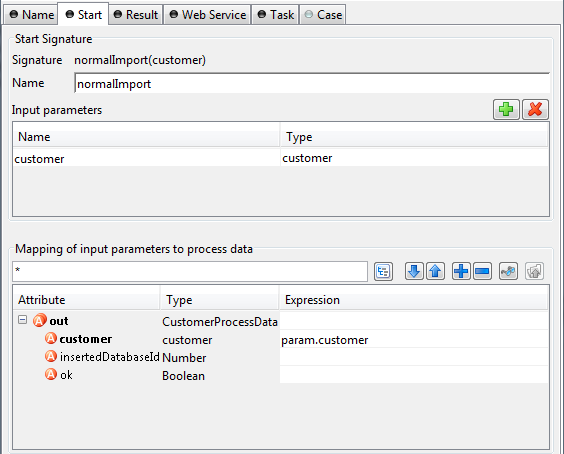
- Start signature
-
The name text field allows you to specify the name of the web service operation. This is the name that will also appear in the generated WSDL and will be used to call the web service operation.
- Input parameters
-
This table is used to define the input parameters of the operation. The list may be left empty if the operation does not require any input parameters. To add a new parameter, click the green plus icon and specify the name and type of the parameter.
Warning
Some restrictions apply to the definition of Web Service process input parameters. Please follow the rules below:
Do not use the interface type
Numberas type for an input parameter. Instead use concrete types likeIntegerorDouble.Do not use complex types that contain a
Listattribute as input parameter (e.g.Employeewith an attributeprojectsof typeList<Project>). Use ajava.util.List(e.g.java.util.List<Project>) as type for such attributes instead.In both cases you can still map the incoming values to process attributes of type
NumberorList<?>in the mapping section. - Mapping of input parameters
-
The input parameters defined above are available as fields on the
paramvariable. You can assign the parameter values to the internal data fields in the table.Note
The reason why you have to assign the incoming parameters to local data is to keep the implementation independent from the declaration. By doing so the implementation can be changed at a later point of time (rename data, use different data types, etc.) while at the same time the web service interface is kept stable. This has the effect that none of the clients of the web service have to be changed/adapted after an internal data change.
This tab is used to define the return parameters of the operation.
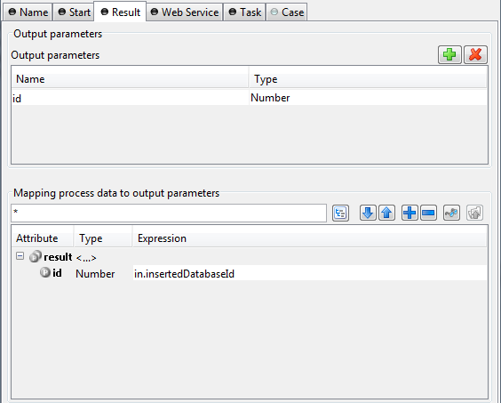
- Output Parameters
-
This table is used to define the output parameters of the operation. The list may be left empty if the operation does not return any data. To add a new parameter, click the green plus icon and specify the name and type of the parameter.
- Mapping of process data
-
For each defined output parameter you must now specify the value that will be returned. In most cases, this is a process attribute. However you may specify any valid IvyScript expression.
This tab is used to change the web service specific settings of the operation.
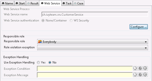
- Web service
-
The web service section shows the web service's name and authentication options. Click the Configure... button to open the configuration dialog. See inscription mask of the web service process for details.
Note
Since these settings are defined per web service and not per web service operation, any changes here will have an impact on all the operations within the same process, i.e. web service.
Tip
Use fully qualified class names to generate specific target namespaces in the WSDL of your web service (e.g.
ch.ivyteam.svn.CustomerServiceas demonstrated on the screenshot above will resulttargetNamespace="http://srv.ivyteam.ch/"in your WSDL) - Responsible role
-
You may specify a role that is required to call this start. If the start is invoked with a user not owning the selected role, an error will occur. The error can be handled by a catching “Error Start”.
- Exception handling
-
The exception handling allows your web service operation to throw a custom exception if your process could not complete normally. When such an exception is thrown, no output parameters are returned to the client.
After activating the exception handling, define the condition on which the exception should be thrown and the message to be returned to the caller.
This tab defines information relevant to the task. The task created for a web service call will normally not appear in a task list of a user. The values on this tab are therefore only relevant for analysing the finished tasks and not for the task list itself.
- Entry in Task List
-
Defines the name and description of the task.
- Priority
-
Here you select the priority of the task.
This tab allows to set additional information to categorize the task created. The values set on this tab are only informational and have no effect on how this task is treated by Axon.ivy.
You can set the name of the business calendar that should be used for this task. In the
context of this task ivy.cal will return this business calendar
regardless of what you've set for the case.
For more information about business calendar administration see the engine guide.
For more information about business calendar usage see the Public API of
ch.ivyteam.ivy.application.calendar.IDefaultBusinessCalendar.
On this tab you can configure the Case created by this Web Service Process Start. See “Case Tab” in the Task Switch Gateway element.
The Web Service endpoints are generated automatically in a Java file which contains JAX-WS annotations to define the Web Service. If the default configuration does not fit your needs, the generated Java file can be managed and extended by the developer.
The Java file is located in the folder
[project]/src_wsproc/[fully-qualified-name].java and gets interpreted
by the CXF library (http://cxf.apache.org/). The file has to
be moved to the src-folder of the project and has to be in line with the
configuration of the WS Start Elements of the process. The
fully-qualified-name is defined in the inscription mask of the
process.
The Java file in the src-folder is under control of the Developer. When a WS
Start element configuration changes, the change has to be adapted manually in the Java
file.
 The User Dialog Start element is located in the
User Dialog drawer of the process editor palette.
The User Dialog Start element is located in the
User Dialog drawer of the process editor palette.
The User Dialog Start element is used to map a Start Method (as declared in the Interface Editor) to the process that is started by this element and that implements the Start Method.
The element allows to initialize internal data of the User Dialog from the input parameters of the call and to define return values from process data (to be returned when the User Dialog finishes).
Note
With Rich Dialogs on the User Dialog Start, embedded inner Rich User Dialogs are initialized by calling individual start methods recursively.
This tab is included in the mask of all process elements and contains the name and a description of the element. See Name Tab for a more detailed description.
This tab is used to select the signature of the Start Method.
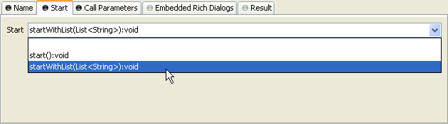
- Start
-
The drop down list allows you to select one of the start methods declared in the interface of the User Dialog. Only methods that have not yet been mapped (i.e. assigned to start elements) are available for selection.
Tip
If the drop down list is empty, then all methods have already been assigned. The additional start element is therefore useless and you can delete it.
This tab is used to map the incoming call parameters to the User Dialog's internal process data.
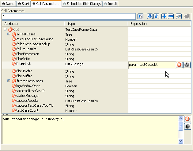
- Call Parameters
-
The call parameters are available as fields on a
paramvariable. You can assign the parameter values to the internal data fields in the table or initialize them with the scripting field below the table. If both the table and the scripting area are used for assignment, then the table's assignments will be executed first.Note
The reason why you have to assign the incoming parameters to local data is to keep the implementation independent from the declaration. The mapping of parameters serves as a flexible adapter mechanism: By doing so the implementation can be changed at a later point of time (rename data, use different data types, etc.) while at the same time the interface is kept stable. This has the effect that none of the clients of the Rich Dialog have to be changed/adapted after an internal data change.
Tip
The variable
panelis not available on the Start Method element for technical reasons: At the execution time of this element the panel is not yet completely initialized. Therefore access to it's components is considered potentially dangerous and prohibited on purpose. - Temporary disabled UI events (only available for Rich Dialogs)
-
If selected, all UI events (like
SELECTION_CHANGED,VALUE_CHANGEDorLIST_SELECTION) are disabled until the start-process reaches its end-step. All disabled events are listed in the enumerationUiEventKind.-
Other rich dialogs (implicitly inner Rich Dialogs) are not affected.
-
The data binding will be executed before the re-enablement.
Note
You have the possibility to disable UI events permanently or temporarily by the API. See the public API,
ivy.rd.disableUiEvents(),ivy.rd.enableUiEvents()andivy.rd.disabeleUiEventsTemporary().Tip
In most cases the panel data (like combo boxes etc.) are fully initialized on startup, for example when you get the whole data from a Web Service etc. But when widget values should be changed when another widget changes, e.g. on value change. In such cases the events could be disabled to speedup the startup behaviour of a panel, because the panel does not have to refresh its data again for each dependency event on the panel at startup.
-
This tab is used to initialize the embedded Rich Dialogs within a Rich Dialog.
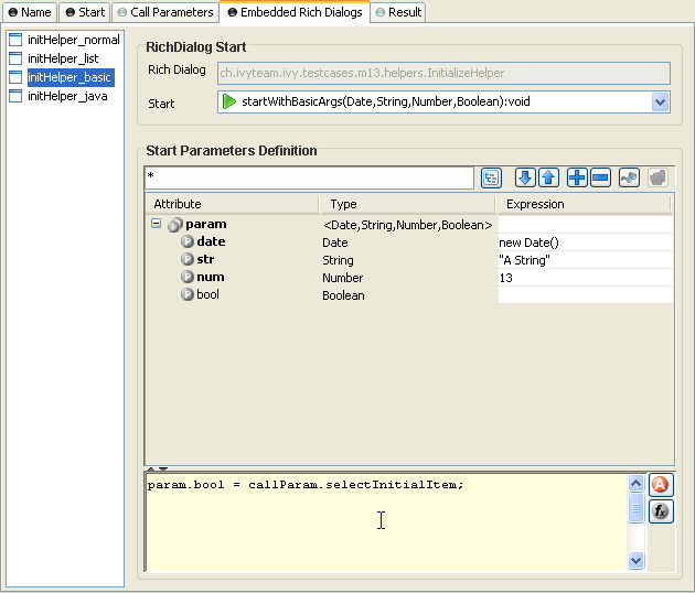
- Embedded Rich Dialogs
-
The embedded Rich Dialog instances can be initialized individually. The column on the left shows all embedded Rich Dialogs that are located on the configured Rich Dialog's panel. For each of them an individual Start Method may be chosen, just as described for the Rich Dialog Element.
Tip
In the context of this tab the
paramvariable is reserved for the arguments of the called start method for this Rich Dialog.If you want to use incoming call parameters values as arguments for the start methods of embedded Rich Dialogs then you can use the
callParamvariable as demonstrated above.
This tab is used to define the return values of the User Dialog.
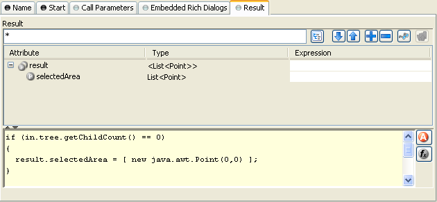
- Result
-
Return values can be defined according to the declared return types that the mapped Start Method specifies. The table on this tab shows a
resultvariable which has fields for each declared return type (none, if the return type isvoid).You can define the returned result values either in the table or by using the IvyScript field below it. The assignments of the table will be executed before the script.
Tip
The defined result object will become available to the caller on the Output tab of the invoking User Dialog Element once the User Dialog has finished.
 The User Dialog Method Start element is located in the Rich
Dialog drawer of the Process editor palette.
The User Dialog Method Start element is located in the Rich
Dialog drawer of the Process editor palette.
The User Dialog method element is used to map a User Dialog method (as declared on the User Dialog's interface) to a process that implements the functionality of that method.
The element allows to set internal data of the User Dialog from the input
parameters of the method call and to define return values either
from process data or by calculation.
This tab is included in the mask of all process elements and contains the name and a description of the element. See Name Tab for a more detailed description.
This tab is used to select the signature of the User Dialog Method that is implemented by this element's process.
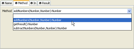
- Method
-
The drop down list allows you to select one of the regular methods declared in the interface of the User Dialog. Only methods that have not yet been mapped (i.e. assigned to method start elements) are available for selection.
Note
If the drop down list is empty, then all methods have already been assigned. The additional method element is therefore useless and you can delete it.
- Temporary disabled UI events
-
If selected, all UI events (like
SELECTION_CHANGED,VALUE_CHANGEDorLIST_SELECTION) are disabled until the method-process reaches its end-step. All disabled events are listed in the enumerationUiEventKind.-
Other User Dialogs (implicitly inner RD's) are not affected.
-
The data binding will be executed before the re-enablement.
Note
You have the possibility to disable UI events permanently or temporarily by the API. See the public API,
ivy.rd.disableUiEvents(),ivy.rd.enableUiEvents()andivy.rd.disabeleUiEventsTemporary(). -
This tab is used to assign the parameter values to the User Dialog's internal data fields.
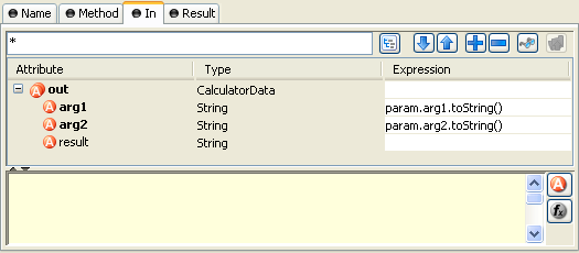
- Mapping
-
Both the table's assignments and any scripting code below the table will be executed at the time of the method call. The table's statements will be executed before the scripting block.
The input parameters are available as fields on a
paramvariable (none if the chosen method does not declare any input parameters). You can assign values to any internal data fields, the assignments do not have to be based onparam.
This tab is used to define the values that will be returned to the caller when the method process finishes.
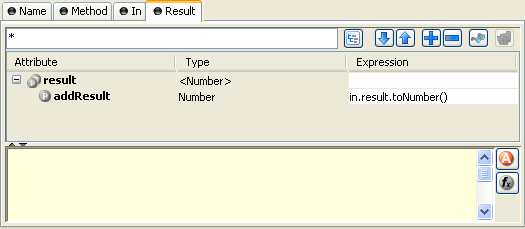
- Method
-
The method's declared return parameters are shown in the table as fields of a
resultvariable (none if the method's return value isvoid).Both the table's assignments and any scripting code below the table will be executed when the method process reaches an User Dialog End Element. The table's statements will be executed before the scripting block.
 The User Dialog Event Start element is located in
the Rich Dialog drawer of the process editor palette.
The User Dialog Event Start element is located in
the Rich Dialog drawer of the process editor palette.
The RD Event Start element represents a process start in the User Dialog logic that is triggered by means of UI event mapping. Events that are fired either by widgets or by embedded Rich Dialogs when the user interacts with the UI may result in the execution of UI processes, if a matching event mapping exists.
This tab is included in the mask of all process elements and contains the name and a description of the element. See Name Tab for a more detailed description.
On this tab you can configure the output of the element (i.e. the data that leaves the element). See Output Tab for a more detailed description.
Note
With Rich Dialogs, additionally to the regular variables of the Output Tab you have the following variables available:
event-
This variable contains an object of the type
java.util.EventObjectthat caused the RD event process to start.Depending on the type of event you may cast this object into different more specific event types. For example to
ch.ivyteam.ivy.richdialog.exec.RdEventif it is an event that was caused by an embedded User Dialog. panel-
This variable contains this User Dialogs panel instance which you can use to set or query any widget properties. It is, however, recommended to use data binding instead of accessing/setting panel properties directly.
On this tab you can execute any IvyScript, e.g. to modify internal data or to define output data of this element. See Code Tab for a more detailed description.
Tip
The entered code will be executed after the execution of the output tab. Although this may seem a bit counter-intuitive at first, you should simply regard the code tab as an alternative way of defining output data. The general recommendation is to use the output table to define simple assignments and the code tab if more extensive scripting is needed to calculate data.
 The User Dialog Broadcast Start element is located
in the User Dialog drawer of the process editor palette. It is only
available in a Rich Dialog.
The User Dialog Broadcast Start element is located
in the User Dialog drawer of the process editor palette. It is only
available in a Rich Dialog.
The Broadcast Start element represents a process start in the Rich Dialog logic that is invoked when an accepted broadcast is received by the Rich Dialog (as declared on the Rich Dialog's interface).
This tab is included in the mask of all process elements and contains the name and a description of the element. See Name Tab for a more detailed description.
This tab is used to select the accepted broadcast event that will trigger this element's process.
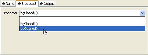
- Broadcast
-
The drop down list allows you to select one of the accepted broadcasts declared in the interface of the Rich Dialog. Only broadcasts that have not yet been mapped (i.e. assigned to broadcast start elements) are available for selection.
Tip
If the drop down list is empty, then all accepted broadcasts have already been assigned. The additional broadcast element is therefore useless and you can delete it.
On this tab you can configure the output of the element (i.e. the data that leaves the element). See Output Tab for a more detailed description.
Note
Additionally to the regular variables of the Output Tab you have the following variables available:
event-
This variable contains an object of the type
java.util.EventObjectthat caused the RD event process to start.You can cast the event object to the type
ch.ivyteam.ivy.richdialog.exec.RdEventin order to access the optional event parameter object that may have been passed along with the event. panel-
This variable contains this Rich Dialogs panel instance which you can use to set or query any widget properties. It is, however, recommended to use data binding instead of accessing/setting panel properties directly. gen
 The User Dialog Script Step
element is located in the User Dialog drawer of the process editor
palette.
The User Dialog Script Step
element is located in the User Dialog drawer of the process editor
palette.
With this element you can perform any transformation of the process data within the User Dialog. In a Rich Dialog you have also access to the panel object.
Warning
It is strongly recommended to use the dedicated process elements if you intend to use specific functionality and/or technology (such as invoking Web Services, querying Databases and so on) as these elements encapsulate their use and handle exceptions internally.
This tab is included in the mask of all process elements and contains the name and a description of the element. See Name Tab for a more detailed description.
On this tab you can configure the output of the element (i.e. the data that leaves the element). See Output Tab for a more detailed description.
Note
In a Rich Dialog, additionally to the regular variables of the Output Tab you have the following variables available:
panel-
This variable contains this User Dialogs panel instance which you can use to set or query any widget properties. It is, however, recommended to use data binding instead of accessing/setting panel properties directly.
On this tab you can modify any properties of the Rich Dialog's panel. See Panel Tab for a more detailed description.
Tip
The modifications on the panel will be performed after the execution of the output tab and before the code tab.
On this tab you can execute any script, e.g. to modify internal data or to define output data of this element. See Code Tab for a more detailed description.
Tip
The entered code will be executed after the execution of the output tab and the panel tab. Although this may seem a bit counter-intuitive at first, you should simply regard the code tab as an alternative way of defining output data. The general recommendation is to use the output table to define simple assignments and the code tab if more extensive scripting is needed to calculate data.
 The User Dialog Fire Event element is located in the User
Dialog drawer of the process editor palette. It is only available with Rich Dialogs.
The User Dialog Fire Event element is located in the User
Dialog drawer of the process editor palette. It is only available with Rich Dialogs.
This element is used to fire events that are declared on the Rich Dialog's interface during process execution.
The range (i.e. the potential receivers) of the fired event is defined by the scope of the event and is part of the event's declaration (see there to learn about what types of scope that are available). A fired event may carry an optional parameter which can be retrieved by the receiving event handlers.
Events can be received in two ways:
If the fired event is a broadcast event then other Rich Dialogs may declare and implement an accepted broadcast that matches the fired event's signature.
If the event is a regular event (i.e. for subscribers only) then an outer Rich Dialog may map the fired event onto one of it's Rich Dialog event start elements using the event mapping mechanism.
Tip
You can also fire Rich Dialog events programmatically by invoking the fireXYZ(...) methods on the Rich Dialog panel (advanced visibility). It is, however, recommended to use the fire event element instead due to the declarative nature of the element inside the process.
This tab is included in the mask of all process elements and contains the name and a description of the element. See Name Tab for a more detailed description.
This tab is used to select the Rich Dialog event that should be fired.
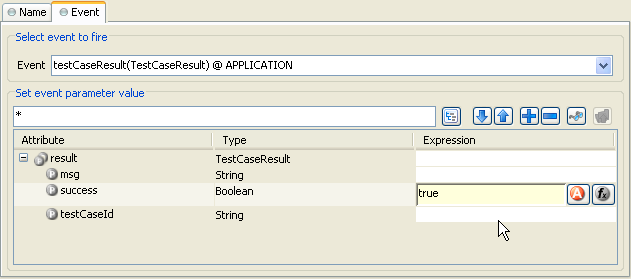
- Event To Fire
-
The drop down list allows you to select one of the events that the Rich Dialog is able to fire (as declared in the interface of the Rich Dialog). The list shows all available events with their name, type of event object and scope.
- Event Parameter Value
-
Depending on the signature of the selected event, an optional event parameter may be attached to the event. The table in this section can be used to assign values to the fields of the specified parameter type (if available).
Leave the table empty if you don't want to set an event parameter (in which case the parameter value will stay null).
Warning
It is strongly recommended to use only immutable objects as event parameter. During the distribution of the fired event all receivers can access the parameter object. If it is mutable and can thus be changed by one receiver then the object will contain different data when it is accessed by the next receiver, which may lead to unpredictable behavior.
 The User Dialog UI Synchronization element is located in the
User Dialog drawer of the process editor palette. It is only available with Rich Dialogs.
The User Dialog UI Synchronization element is located in the
User Dialog drawer of the process editor palette. It is only available with Rich Dialogs.
This element can be used to update the user interface on the client during a long running process on the server.
Problem: If a long running UI process is started on the server (e.g. by clicking on a button) then the user interface on the client will not be updated until the process on the server has finished, because the request will not return to the client until then. It doesn't matter whether the process performs changes on the UI (e.g. by setting a text on a label or by updating the value of a progress bar) during it's execution, those changes will not be transmitted to the client until the request returns.
Solution: If you insert the UI Synchronization element at some points inside your long running process then the changes that were set on the UI are transmitted to the client. The currently running request will temporarily return, update the client's user interface, and then immediately come back and resume the long running process.
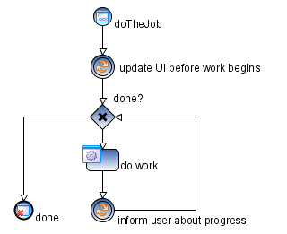
Note
Use the data binding for UI update. Both an upbinding (i.e. Data-to-UI) and a downbinding (i.e. UI-to-Data) will be executed automatically every time when a Rich Dialog UI Synchronization element is executed.
Warning
Do not use the UI Synchronization element inside a Rich Dialog start method.
This will not work for technical reasons, because the initialization of the Rich Dialog will not have been completed at this point of time. If you want to execute a long running process immediately after a Rich Dialog is started then you should move this logic to an event process.
This process should then be triggered by invoking a hidden button (i.e. a button
on the panel with the property visible = false) with
ivy.rd.clickDeferred(hiddenButton). The button will automatically
be clicked on the client as soon as the current request has ended, thus immediately
sending another request to the server. The following figure illustrates this:
Have a look at the UI Refresh demo (particularly the Progress Dialog part) in the IvyDemos project for an example on how to do this.
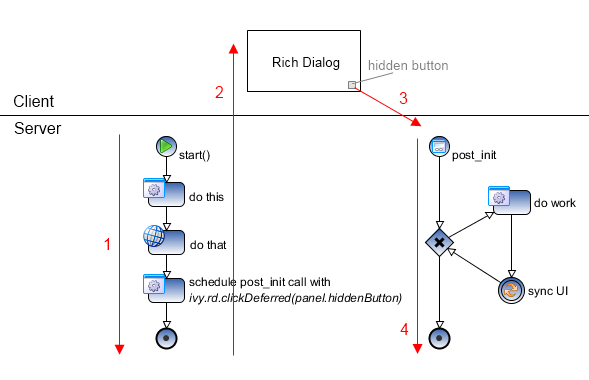
Explanation: [1] Start method of Rich Dialog initializes
the Rich Dialog. At the end of the init method a call to
ivy.rd.clickDeferred(..) is used to schedule the clicking of a
hidden button at a later point of time. [2] Rich Dialog is uploaded to the client
and displayed. [3] Immediately after the Rich Dialog becomes visible, the scheduled
click on the hidden button is executed and triggers another server round trip. [4]
The post_init event handler (which is associated
with the hidden button) is executed and performs the potentially long running task,
where the UI Synchronization element may safely
be used.
This tab is included in the mask of all process elements and contains the name and a description of the element. See Name Tab for a more detailed description.
 The User Dialog Process End element is located in the User
Dialog drawer of the process editor palette.
The User Dialog Process End element is located in the User
Dialog drawer of the process editor palette.
This element is used to terminate any User Dialog processes inside the User Dialog's logic.
Note
An up-binding (i.e. data-to-panel) will be executed automatically every time when a User Dialog process end element is executed.
This tab is included in the mask of all process elements and contains the name and a description of the element. See Name Tab for a more detailed description.
 The User Dialog Exit End element is located in the Rich
Dialog drawer of the process editor palette.
The User Dialog Exit End element is located in the Rich
Dialog drawer of the process editor palette.
This element is used to terminate the execution of a User Dialog.
If process execution reaches this element then the User Dialog's panel is immediately removed from the display container that it resides in. The result tab code of the originally invoked start method is executed and the calculated results are passed back to the User Dialog element which called the User Dialog. Afterwards the calling process continues.
Note
If the User Dialog was called asynchronously then the User Dialog's panel will simply be removed from the UI and the calculated result value of the earlier invoked start method will be ignored.
This tab is included in the mask of all process elements and contains the name and a description of the element. See Name Tab for a more detailed description.
The BPMN Activity drawer contains elements, that can be used to design a process at a high level, where details of the technical implementation are hidden inside the element itself. Thus BPMN Activities behave similar to a Embedded Sub, but their purpose is different.
They are intensively used by the importer of Axon.ivy Modeler Processes.